Pulsed optical threat detection

a technology of pulsed lasers and optical threats, applied in the field of laser pulse detection methods, can solve the problems of fpa sensitivity, the most dangerous threat to the optical radiation sensor system, and the detector surface of this type of sensor is most vulnerable to such threats,

Inactive Publication Date: 2000-05-30
UNITED STATES OF AMERICA THE AS REPRESENTED BY THE SEC OF THE ARMY
View PDF1 Cites 2 Cited by
  • Summary
  • Abstract
  • Description
  • Claims
  • Application Information

AI Technical Summary

Problems solved by technology

On the modern battlefield one of the most dangerous threats to optical radiation sensor systems is the pulsed laser.
The detector surface of this type of sensor is most vulnerable to such threats since it is this surface that all incoming radiation impinges upon.
The external detectors have lower sensitivity than the FPA, have noise problems, and are an additional cost.
While the prior art has reported using separate detectors none have established a basis for a specific technique that is dedicated to the task of resolving the particular problem at hand.

Method used


Image

  • Pulsed optical threat detection
  • Pulsed optical threat detection
  • Pulsed optical threat detection

Examples


Embodiment Construction

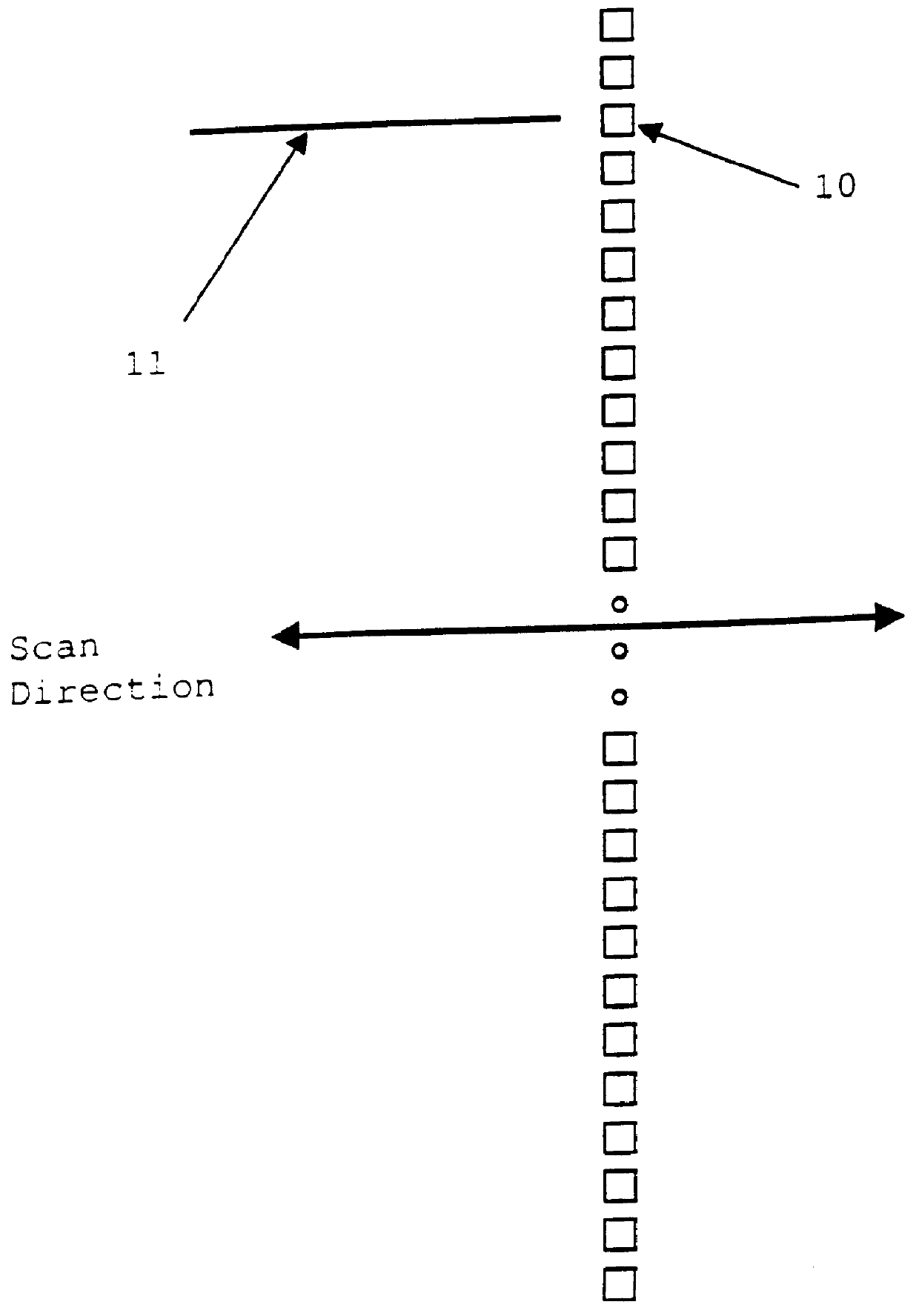
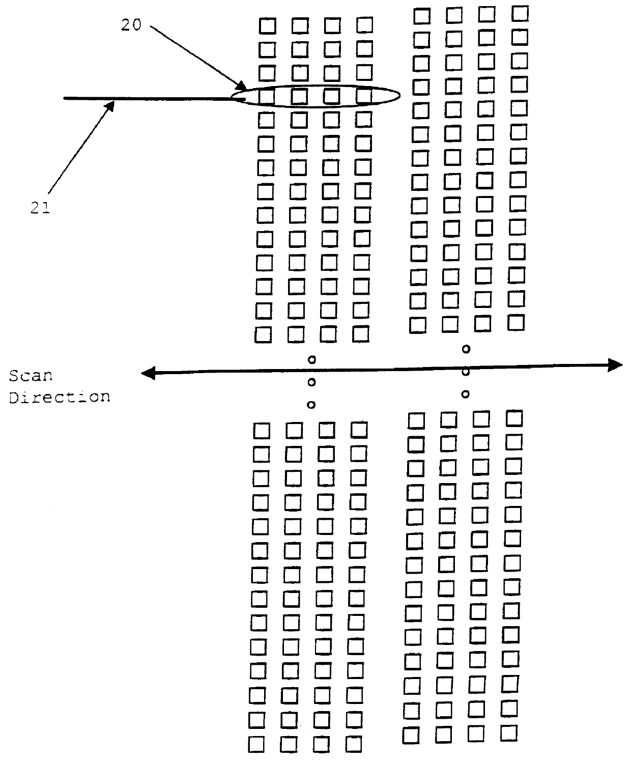
Referring now to the drawings, and more particularly to FIGS. 1 and 2 there are shown the FPA layouts for a first and second generation FLIR system respectively. The squares shown in both FIGS. 1 and 2 are representations of individual detector elements of the FPA. In FIG. 1, the detector elements are scanned perpendicular to the detector array. The output of each detector element 10 forms a line 11 in the display image as the infrared scene is scanned across the FPA. The technique illustrated in FIG. 1 is typical for a first generation FLIR system. In FIG. 2 the detector elements are grouped to form individual display pixels, such as group 20, in a staggered array layout. The detector elements shown in FIG. 2. are scanned perpendicular to the FPA axis. Each display pixel is generated after the output of the group of four detector elements are combined by time delay integration (TDI). Each TDI group forms a display line 21 as the infrared scene is scanned across the FPA. The techniq...


PUM


Abstract

A technique for internal forward looking infrared (FLIR) system detection of laser pulses. For scanning systems image pixel output of each frame is sampled as image data which is used to determine a pattern of saturated image pixels. The pattern of saturated image pixels is compared to predetermined laser pulse patterns and is then analyzed to determine if a laser pulse was detected. For staring systems, the patterns are compared to previous and following frames to determine if short lived large changes occur to determine if a laser pulse was detected.

Description

DESCRIPTION1. Field of the InventionThe present invention generally relates to optical emission detection methods and more specifically, to laser pulse detection methods in FLIR systems.2. Description of Prior ArtOn the modern battlefield one of the most dangerous threats to optical radiation sensor systems is the pulsed laser. The detector surface of this type of sensor is most vulnerable to such threats since it is this surface that all incoming radiation impinges upon. For the forward looking infrared (FLIR) system the detector surface is the focal plane array (FPA). The previous method to detect laser pulses in FLIR systems was to provide several detectors external to the FPA specifically designed to detect laser pulses. The external detectors have lower sensitivity than the FPA, have noise problems, and are an additional cost.While the prior art has reported using separate detectors none have established a basis for a specific technique that is dedicated to the task of resolvin...

Claims


Application Information

Patent Timeline
Patent Type & Authority Patents(United States)
IPC IPC(8): G01S7/483G01S7/48
CPCG01S7/483
Inventor COLANDENE, THOMAS M.SONSTROEM, JAIME
Owner UNITED STATES OF AMERICA THE AS REPRESENTED BY THE SEC OF THE ARMY
Why Eureka
Try Eureka