Print head pulsing techniques for multicolor printers

a multi-color printer and print head technology, applied in the field of digital printing system, can solve the problems of insufficient control of print head, increase complexity and cost, and decrease the convenience of such printing systems, and achieve the effect of reducing the peak power requirements of print head and coincidence of pulses

Active Publication Date: 2006-12-28
ZINK IMAGING
View PDF90 Cites 22 Cited by
  • Summary
  • Abstract
  • Description
  • Claims
  • Application Information

AI Technical Summary

Benefits of technology

[0020] In one aspect of the invention there is disclosed a multicolor thermal imaging system wherein different heating elements on a thermal print head can print on different color-forming layers of a multicolor thermal imaging member in a single pass. The line-printing time is divided into portions, each of which is divided into a plurality of subintervals. All of the pulses within the portions have the same energy. In one embodiment, every pulse has the same amplitude and duration. Different colors are selected for printing during the different portions by varying the fraction of subintervals that contain pulses. This technique allows multiple colors to be printed using a thermal print head with a single strobe signal line. Pulsing patterns may be chosen to reduce the coincidence of pulses provided to multiple print head elements, thereby reducing the peak power requirements of the print head.

Problems solved by technology

The use of donor members with multiple different color patches or the use of multiple donor members increases the complexity and the cost, and decreases the convenience, of such printing systems.
In some instances this method for controlling the print head may not be completely satisfactory.
Examples of techniques for performing such stitching are disclosed in the above-referenced patent application entitled “Image Stitching for a Multi-Head Printer.” It is not, however, possible to accomplish effective screening using the pulse patterns just described with conventional thermal print heads.
However, the down-web displacement of the pixels may cause the first time segment of some pixels to overlap the second time segment of others, requiring that some pixels be supplied with a low duty-cycle strobe pulse at the same time that others are being supplied with a high duty-cycle strobe pulse.
As described above, the use of a single or a small number of strobe signal(s) for all print head elements in a print head may make it impossible to provide such varying pulse duty cycles across print head elements in the same subinterval.
This typically results in the choice of a larger and more expensive power supply than would be required to fulfill the “average” power demand.

Method used


Image

  • Print head pulsing techniques for multicolor printers
  • Print head pulsing techniques for multicolor printers
  • Print head pulsing techniques for multicolor printers

Examples


Embodiment Construction

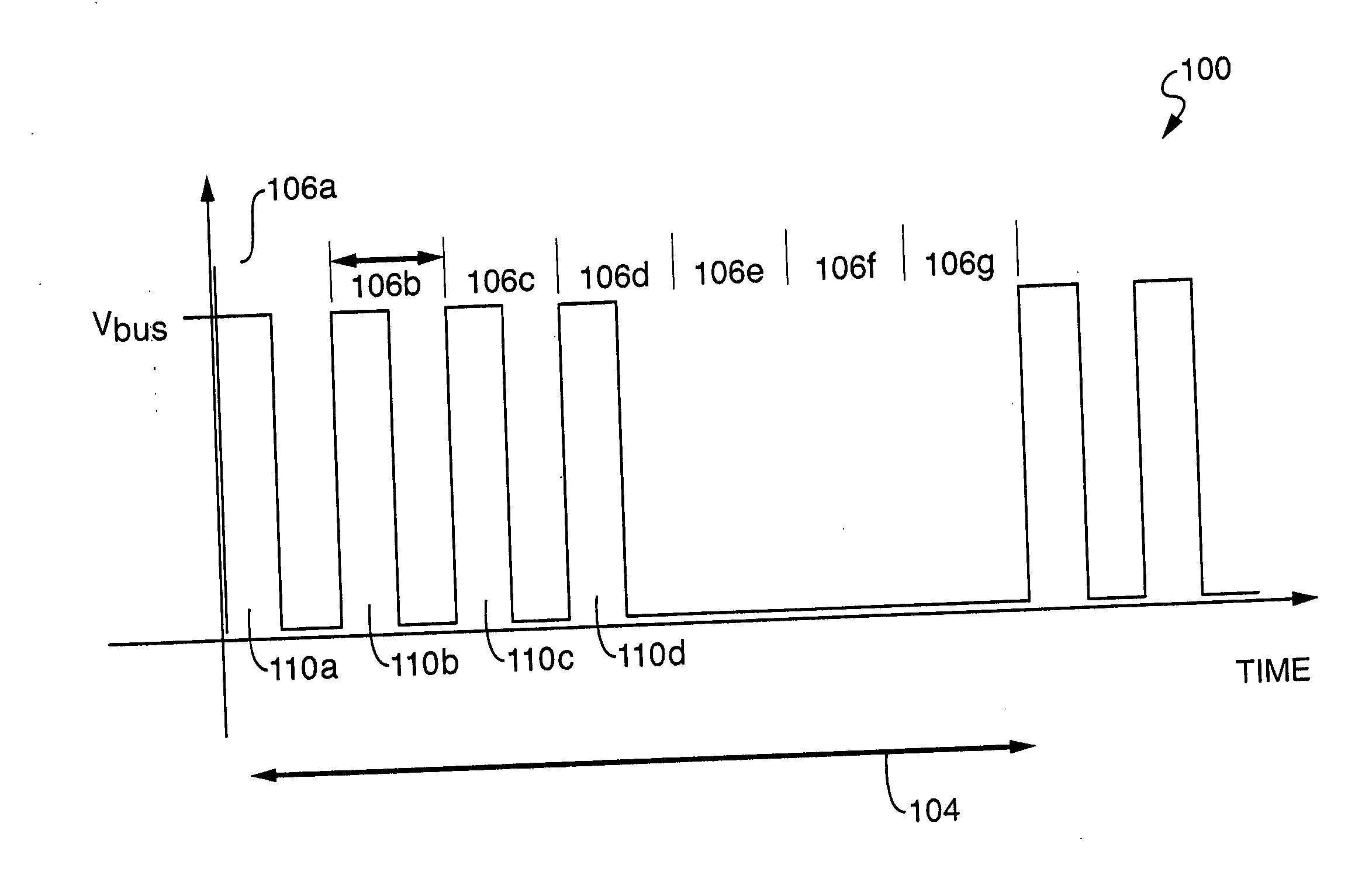
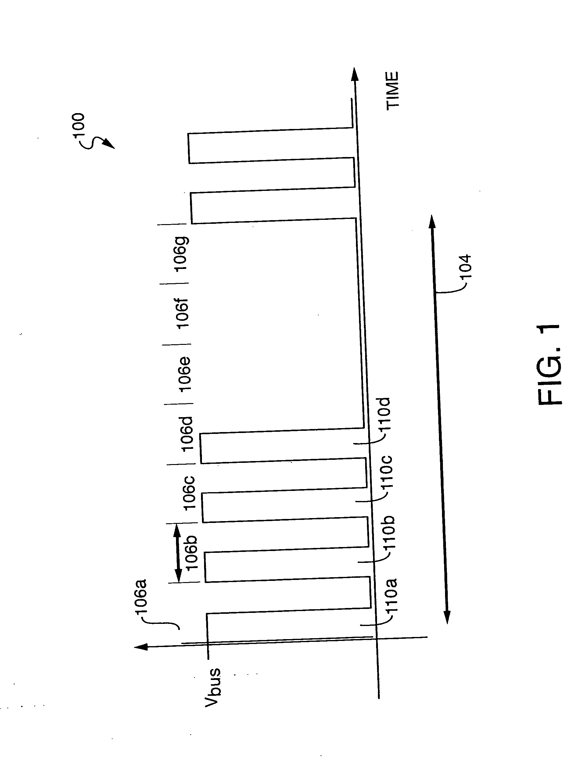
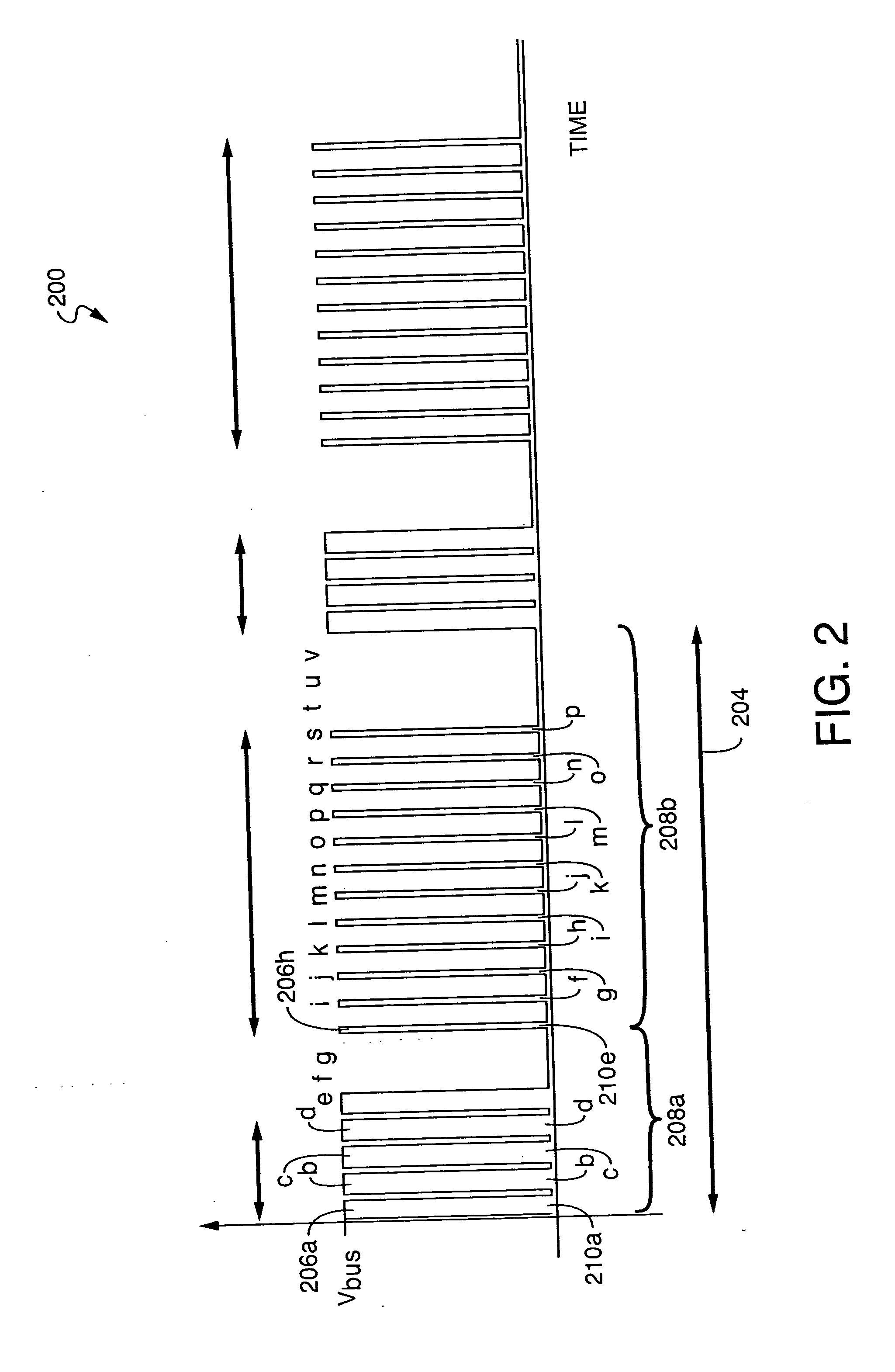
[0042] In one aspect of the invention there is disclosed a multicolor thermal imaging system wherein different heating elements on a thermal print head can print on different color-forming layers of a multicolor thermal imaging member in a single pass. The line-printing time is divided into portions, each of which is divided into a plurality of subintervals. All of the pulses within the portions have the same energy. In one embodiment, every pulse has the same amplitude and duration. Different colors are selected for printing during the different portions by varying the fraction of subintervals that contain pulses. This technique allows multiple colors to be printed using the same strobe pulses. Pulsing patterns may be chosen to reduce the coincidence of pulses provided to multiple print head elements, thereby reducing the peak power requirements of the print head.

[0043] For example, referring to FIG. 3, a graph 300 is shown which plots the voltage across a single print head elemen...


PUM


Abstract

In one aspect of the invention there is disclosed a multicolor thermal imaging system wherein different heating elements on a thermal print head can print on different color-forming layers of a multicolor thermal imaging member in a single pass. The line-printing time is divided into portions, each of which is divided into a plurality of subintervals. All of the pulses within the portions have the same energy. In one embodiment, every pulse has the same amplitude and duration. Different colors are selected for printing during the different portions by varying the fraction of subintervals that contain pulses. This technique allows multiple colors to be printed using a thermal print head with a single strobe signal line. Pulsing patterns may be chosen to reduce the coincidence of pulses provided to multiple print head elements, thereby reducing the peak power requirements of the print head.

Description

CROSS REFERENCE TO RELATED APPLICATIONS [0001] The present application is related to the following commonly assigned applications and patents, which are incorporated by reference herein in their entirety: [0002] U.S. patent application Ser. No. 10 / 374,847, filed on Feb. 25, 2003, Attorney Docket No. C-8566, entitled “Image Stitching for a Multi-Head Printer”; [0003] U.S. patent application Ser. No. 10 / 151,432, filed on May 20, 2002, entitled “Thermal Imaging System”, now U.S. Pat. No. 6,801,233; [0004] U.S. patent application Ser. No. 10 / 990,672, entitled “Method and Apparatus for Controlling the Uniformity of Print Density of a Thermal Print Head Array”; and [0005] U.S. Pat. No. 6,661,443 to Bybell and Thornton, issued on Dec. 9, 2003, entitled “Method and Apparatus for Voltage Correction.”BACKGROUND [0006] 1. Field of the Invention [0007] The present invention relates generally to a digital printing system and, more generally, to techniques for pulsing energy to print heads in a p...

Claims


Application Information

Patent Timeline
Patent Type & Authority Applications(United States)
IPC IPC(8): B41J2/40
CPCB41J2/355B41J2/36
Inventor LIU, CHIENVETTERLING, WILLIAM T.
Owner ZINK IMAGING
Why Eureka
Try Eureka