

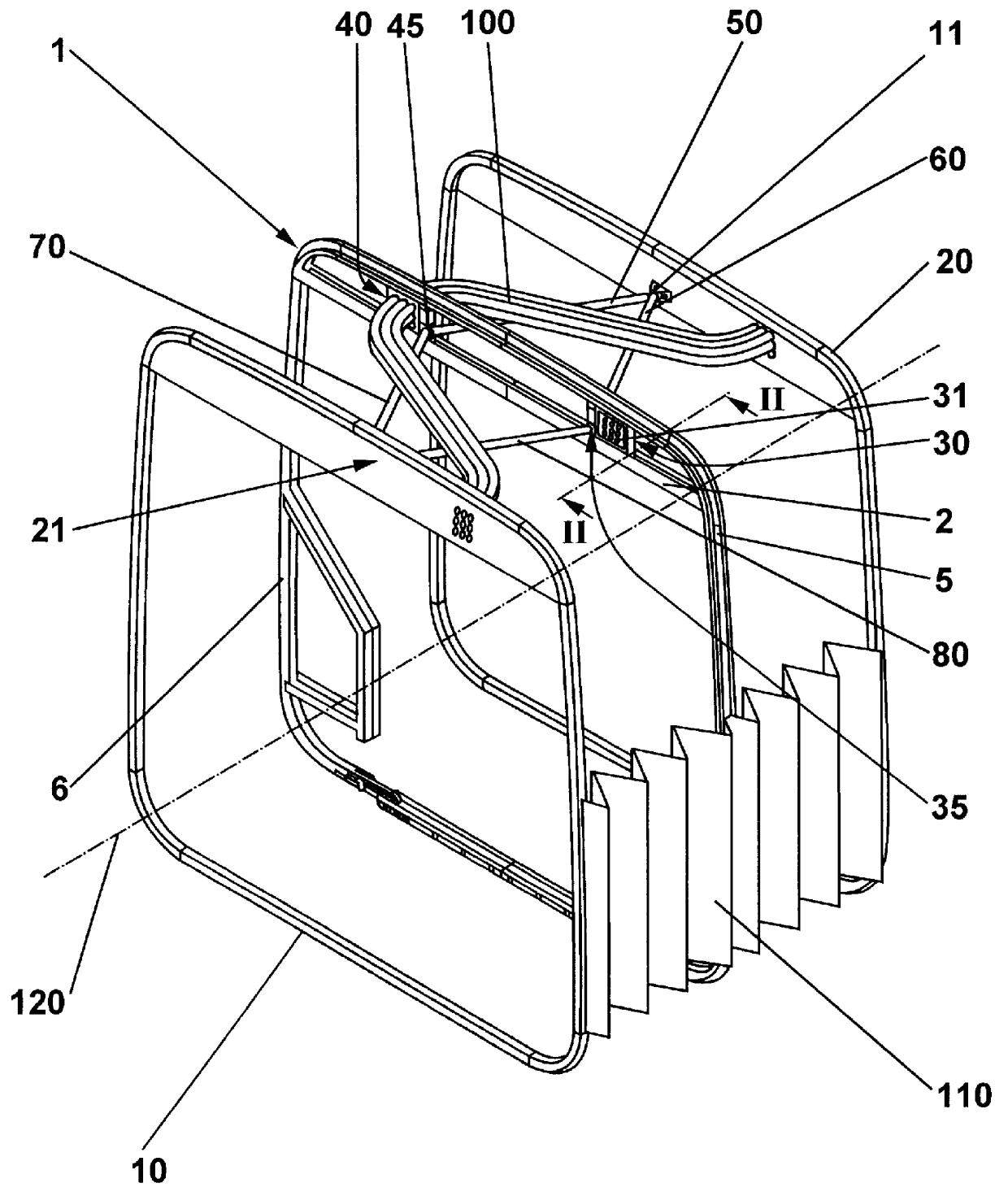
Central frame of a connecting corridor bellows subdivided in two halves
- Summary
- Abstract
- Description
- Claims
- Application Information
AI Technical Summary
Benefits of technology
Problems solved by technology
Method used
Image

Examples
second embodiment
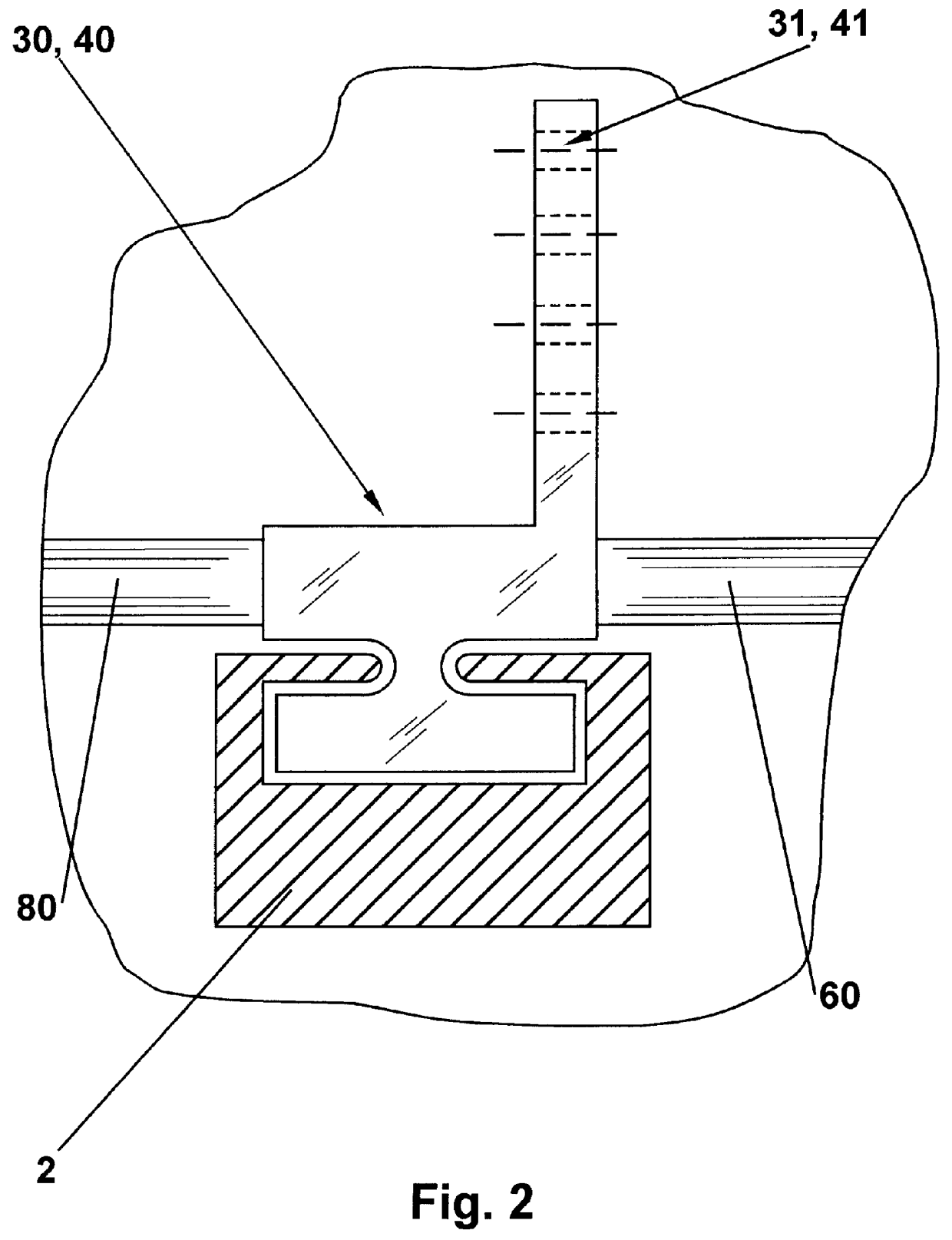
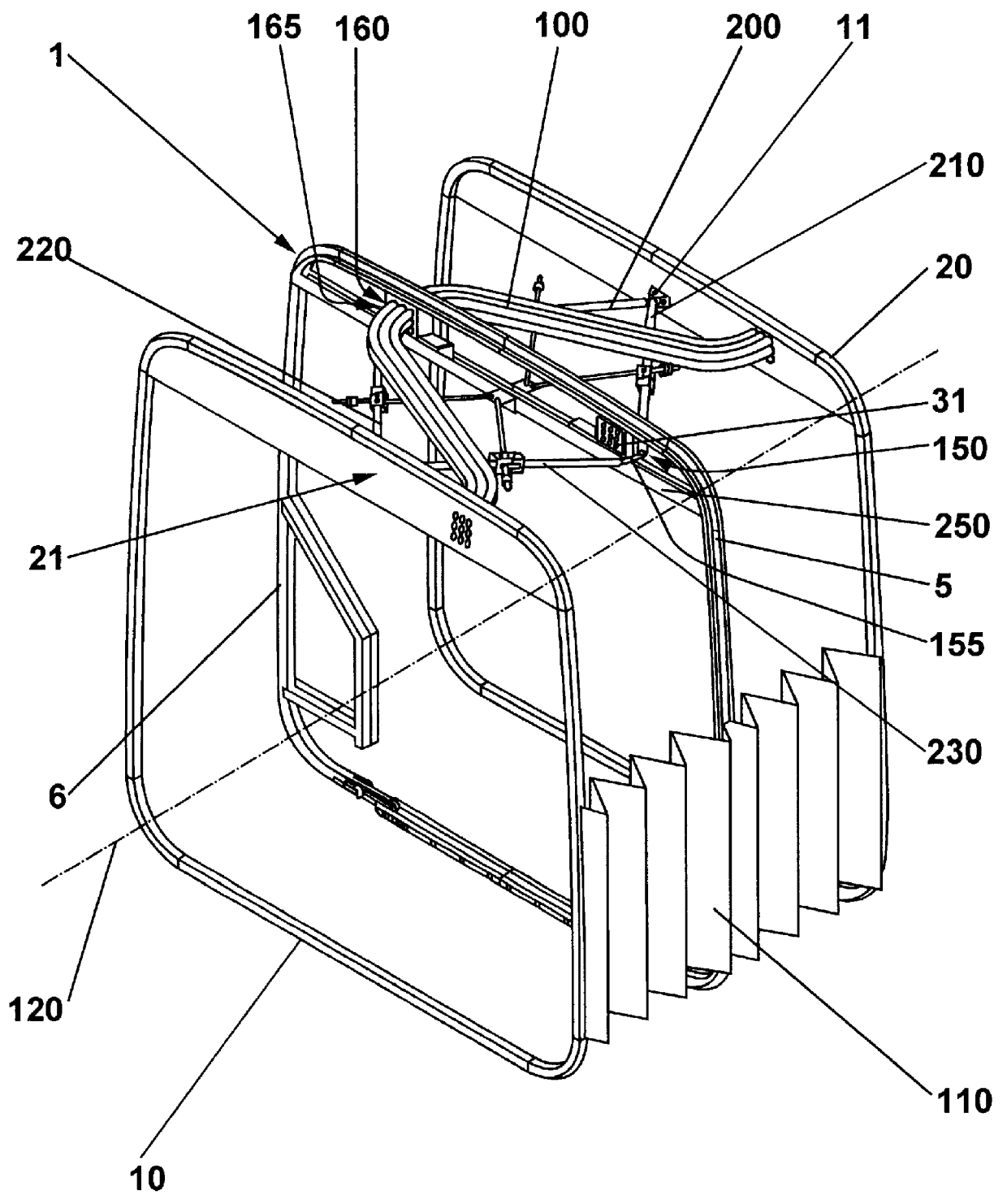
a central frame stabilization can be seen in the FIGS. 3 to 6. According to FIG. 3, the cradles 150 and 160 are movably guided in the guiding rail referred to with numeral 250, whereas the cradles 150, 160 are provided with hinged guiding members 200 to 230, in analogy with the embodiment according to the FIGS. 1 and 2. These guiding members 200, 210, 220, 230 are not only hinged to the cradles 150, 160 at 155, 165, they are also hinged to the corresponding vehicle part 10, 20 at 11, 21. In this respect, the structural design is identical to the embodiment according to the FIGS. 1 and 2. The difference consists in the fact that each guiding member 200 to 230 has a joint 201, 211, 221, 231. Each joint has a stopper 202, 212, 222, 232; the stopper has been designed so that in the area where the joint divides into the two joint elements 201a, 201b or 211a, 211b or 221a, 221b or 231a, 231b it is provided with a bevel 205 to 235, so that the two joint elements are adjacent when the joint...
PUM
 Abstract
Description
Claims
Application Information