Thin wall, high pressure, volume compensator

a technology of volume compensator and thick wall, applied in the direction of fluid-pressure actuator, accumulator installation, pipe/joint/fitting, etc., can solve the problems of virtually undetectable deflection, small deflection, and inability to measure the deflection

Inactive Publication Date: 2000-06-20
SENIOR ENG INVESTMENTS
View PDF52 Cites 109 Cited by
  • Summary
  • Abstract
  • Description
  • Claims
  • Application Information

AI Technical Summary

Problems solved by technology

Depending upon the stiffness of the system, the deflection may be so small, even under substantial pressure differentials, as to be virtually undetectable.
Alternatively, if the system is not very stiff, measurable deflection may occur with even relatively small pressure differentials.
That is, a metal diaphragm is not capable of accommodating deflection magnitudes and / or cycling required of higher pressure systems, before failure, while a rubber diaphragm (if backed by a pressurized gas), can withstand greater magnitude deflections and cycling.
However, such prior art metal bellows accumulator constructions incur, of necessity, substantial costs in terms of actual material used as well as in the fabrication efforts required to manufacture such accumulators, including pressurized canisters as well as the specialized shaping of the individual convolutions and the requirement for welds at each connection between individual diaphragm members.
However, as the wall thickness increases, so does the susceptibility of the wall to high displacement bending fatigue.
However, such prior art metal bellows accumulator constructions incur, of necessity, substantial costs in terms of actual material used as well as in the fabrication efforts required to manufacture such bellows, including the specialized shaping of the rings and the requirement for forming the bellows with the rings on or splitting the rings for assembly.
In addition, the relatively large thickness to diameter ratio (of thickened bellows), makes these bellows construction susceptible to fatigue from numerous extensions and compressions, and / or overly rigid and unresponsive to rapid system fluent material pressure fluctuations.
Reinforced thin-walled bellows also suffer from the potential drawback that the reinforcement is not continuous, but is focused only in specific regions of the bellows.
Further, since only gas is used to support the resilient material, the apparatus of the Rohde '262 reference is not configured for high pressure systems or situations with large pressure differentials across the thickness of the resilient material.

Method used


Image

  • Thin wall, high pressure, volume compensator
  • Thin wall, high pressure, volume compensator
  • Thin wall, high pressure, volume compensator

Examples


Embodiment Construction

While this invention is susceptible of embodiment in many different forms, there is shown herein in the drawings and will be described in detail several specific embodiments, with the understanding that the present disclosure is to be considered as an exemplification of the principles of the invention and is not intended to limit the invention to the embodiments illustrated.

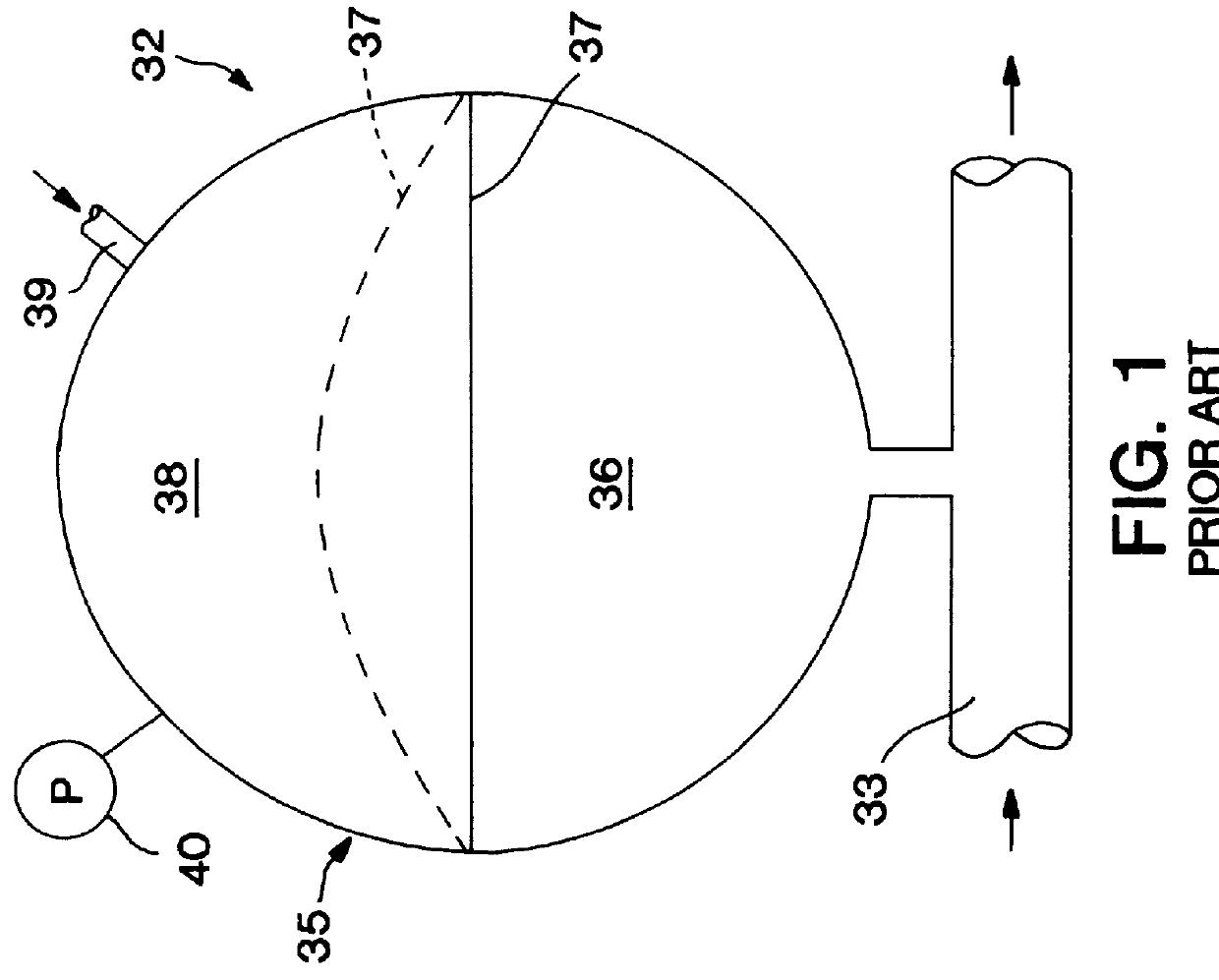
FIG. 4 illustrates schematically a representative environment for the accumulator / compensator apparatus of the present invention. Pressurized fluent material system 60 includes fluid pump 62, fluid transmission line 64, accumulator 66, and the functional system 68, which may be, for example, a power steering unit or braking unit for an automobile. The accumulator / compensator apparatus of the present invention may also be employed in other pressurized fluent material systems, involving pressurized liquids, gases or slurries, and may be suitably adapted to specific applications by one of ordinary skill in the art h...


PUM


Abstract

Accumulators/compensators for pressurized fluent material systems are provided, in which a continuous substantially non-permeable, flexible membrane (like a bellows) surrounds or is surrounded by a non-gaseous support medium, all within a surrounding housing. Various combinations of support media, which may include internal gas-filled cavities, are described and illustrated.

Description

1. Field of the InventionThe present invention relates to accumulators / compensators for pressurized fluent material lines (wherein the fluent material may be a gas, a liquid, a slurry or even a finely particulate material), such as may be found in heavy machinery, such as earth moving equipment, or other machines which incorporate hydraulic fluid lines or other pressurized lines.2. The Prior ArtHigh pressure fluent material systems, for example hydraulic power transmission lines, brake fluid transmission lines and the like, typically operate in pressure ranges from a few hundreds to several thousands of pounds per square inch. Such fluent material transmission systems can be subjected from time to time to rapid pressure fluctuations which may be of substantial amplitude and frequency. An example of such fluctuations exists in the fluent material transmission systems associated with ABS braking systems which pulsate rapidly during hard braking.In such high pressure fluent material sy...

Claims


Application Information

Patent Timeline
Patent Type & Authority Patents(United States)
IPC IPC(8): F16L55/04
CPCF15B1/103F16L55/04F15B2201/3153F15B2201/205
Inventor CARNEY, THOMAS JAMES
Owner SENIOR ENG INVESTMENTS
Why Eureka
Try Eureka