Mobile article support device

a support device and mobile technology, applied in the direction of machine supports, domestic articles, applications, etc., can solve the problems of unnecessarily cumbersome, practically impossible displacement of articles on the support surface,

Inactive Publication Date: 2000-06-20
RICHTER HERBERT
View PDF7 Cites 129 Cited by
  • Summary
  • Abstract
  • Description
  • Claims
  • Application Information

AI Technical Summary

Problems solved by technology

Although this support device operates effectively, it may not be suitable for all support applications, or it may be considered to be unnecessarily cumbersome by some users as the clamping walls have to be moved for depositing an article on, or removing it from, the support device.
With the raised area extending around the article, displacement of the article on the support surface is practically impossible.

Method used


Image

  • Mobile article support device
  • Mobile article support device
  • Mobile article support device

Examples


Embodiment Construction

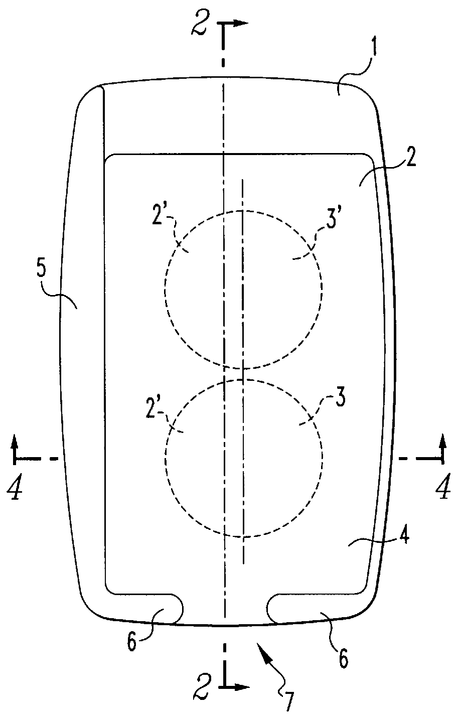
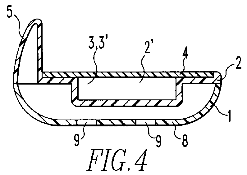
As can be seen from the figures the support device comprises a base body 1 with a support plate 2 for supporting an article which is not shown. The bottom plate 2 includes two recesses 2' in which two cylindrical permanent magnets 3, 3' are firmly received. The upper surface of the permanent magnets 3, 3' is disposed in the same plane as the top side of the bottom plate 2. On the top of the support plate 2 and the magnets 3, 3', there is a non-skid layer 4 of a resilient rubber which covers the support surfaces of the support device.

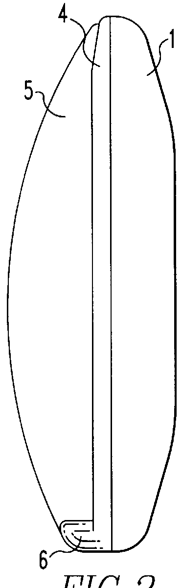
The base body 1 and the support plate 2 are rectangular in shape. An upstanding web 5, 6 extends along two adjacent side edges of the support surface so as to provide side walls 5, 6 extending at a right angle with respect to each other. The side wall 6 extending along a transverse edge includes a recess 7 permitting passage for example of a power cord for a mobile telephone placed onto the support device.

At its bottom wall 8 opposite the support plate 2...


PUM


Abstract

In a support device for supporting mobile articles, particularly for supporting a mobile-telephone in a motor vehicle, which includes a support base having a support plate with a support surface, permanent magnets are embedded in the support surface for holding an article consisting at least partially of a magnetic material which is placed onto the support surface, in firm engagement with the support surface.

Description

The invention relates to a mobile telephone support device which includes a base body to be mounted on a support surface for firmly retaining an article such as a mobile telephone.With the increasing use of cellular telephones such support devices are becoming quite popular recently particularly for supporting cellular telephones in motor vehicles. Generally, such support devices include side walls which are pulled together by springs whereby an article or a telephone is engaged between the side walls. Also, support devices have become known which have side walls which can be moved toward each other against the force of a spring and which can be locked in various positions in which they engage an article or telephone therebetween. This arrangement has the advantage that the article can be released by unlocking the side walls so that they are moved apart by the spring and, in their rest positions, the side walls are disposed apart so that the article can be easily placed between the ...

Claims


Application Information

Patent Timeline
Patent Type & Authority Patents(United States)
IPC IPC(8): B60R11/02B60R11/00
CPCB60R11/00B60R11/0241B60R2011/007
Inventor RICHTER, HERBERT
Owner RICHTER HERBERT
Why Eureka
Try Eureka