Modular cross-connect panel for data networks

a technology of data network and cross-connect panel, which is applied in the direction of electrical apparatus, connection, coupling device connection, etc., can solve the problems of affecting the service life of the rear portion of the cross-connect panel

Inactive Publication Date: 2000-06-20
NEXANS
View PDF12 Cites 42 Cited by
  • Summary
  • Abstract
  • Description
  • Claims
  • Application Information

AI Technical Summary

Benefits of technology

said contact springs are carried by an insulating insert itself mounted on a front portion of the card of said printed circuit having said contact springs firstly connected to said printed circuit and secondly projecting obliquely crossing the insert and extending towards the rear of the printed circuit card, thereby enabling them to be received in said front body of an RJ45 jack.

Problems solved by technology

The operations of fixing cables to the rear portion of the cross-connect panel and of connecting said cables to the connectors of the panel are often lengthy and difficult.
In addition, it is observed that the rear portion of the cross-connect panel often gives rise to the cables being injured or subjected to excessive stresses, depending on whether they come up from the floor or down from the ceiling.

Method used


Image

  • Modular cross-connect panel for data networks
  • Modular cross-connect panel for data networks
  • Modular cross-connect panel for data networks

Examples


Embodiment Construction

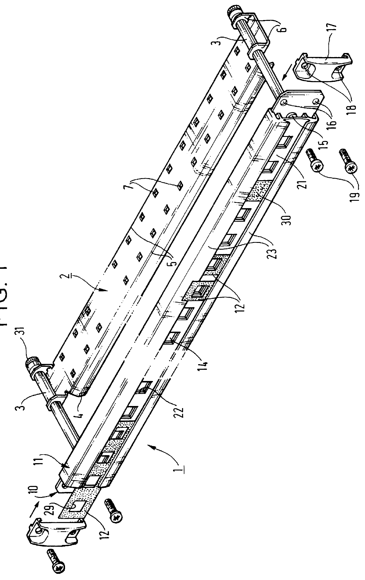
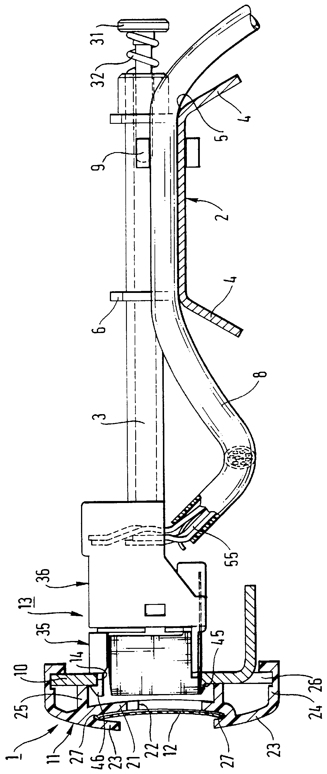
With reference to FIGS. 1 and 2, it can be seen that the cross-connect panel of the invention comprises a support assembly having a vertical front portion 1, a horizontal rear portion 2, and two horizontal columns 3 for assembling the rear portion to the front portion.

The rear portion 2 is a metal plate constituting a rear cable support, and both its longitudinal edges 4 are folded towards the same side of the initial plate, thereby forming two longitudinal rounded fold lines 5 thereon, with the exception of the end portions of said edges which are folded towards the other side of the initial plate, and define two pairs of tabs 6 for fastening the rear cable support 2. Each tab 6 is pierced by a hole, with the holes in the two tabs 6 of each pair being in register and receiving a respective one of the two assembly columns 3.

The rear cable support is thus substantially of channel section to give it good stiffness. It has two longitudinal series of holes 7 formed through the web of it...


PUM


Abstract

The modular cross-connect panel for cable lines of cabled networks comprises a support assembly defining a vertical front portion and a horizontal rear portion, together with female connectors retained on the front portion and connected to the lines of cables fixed on the rear portion. In the panel said support assembly comprises two separate rigid supports referred to as a "front" support and as a "rear" support, together with two assembly columns fixed to the front support and releasably holding the rear support. The panel is applicable to a distribution frame for use in operating cable networks.

Description

The present invention relates to managing cable data networks in buildings. It relates more particularly to a cross-connect panel for use in a distribution frame that may be in the form of a wall cabinet, a rack, or a bay, for the purpose of managing initially cabled data networks.In such video and / or computer and / or telephone data networks, the term "inlet cable" is used below to designate a multiline cable on the source side, i.e. connected to a source of data or to an exchange, the term "trunk cable" is used to designate a likewise multiline cable for transmission from one distribution frame to another, generally from one floor to another or possibly from one building to another, and the term "user cable" issued to designate a single line cable connected to a fixed user jack for connection to a piece of equipment.These various types of cable may all be symmetrical pair electric cables. They terminate at the rear of distribution frames. The cables serving one of the distribution f...

Claims


Application Information

Patent Timeline
Patent Type & Authority Patents(United States)
IPC IPC(8): H01R13/516H01R13/518H04Q1/02H04Q1/14H01R9/24
CPCH04Q1/136H01R13/518H01R9/2416H04Q1/148
Inventor LECOMTE, DIDIER
Owner NEXANS
Why Eureka
Try Eureka