Transmission line hanger

a technology of transceiver and hanger, which is applied in the direction of maintaining the distance between parallel conductors, machine supports, other domestic objects, etc., can solve the problems of deformation and bulging of the hanger section, reducing the life of the hanger, etc., and achieves the effects of reducing stress in the plastic hanger section, limiting deformation, and limiting deformation

Inactive Publication Date: 2000-06-27
COMMSCOPE TECH LLC
View PDF41 Cites 59 Cited by
  • Summary
  • Abstract
  • Description
  • Claims
  • Application Information

AI Technical Summary

Benefits of technology

In summary, the claimed hanger includes several unique features. The gripping ribs reduce the need to tightly clamp the transmission line; thus, they help reduce stress in the plastic hanger sections despite a range of transmission line diameters being accommodated. The snap clasp is designed to limit the deformation which can occur over time as a result of the claimed hanger being able to accommodate a range of transmission line diameters. The snap clasp is also designed to limit deformation due to environmental variations. The alignment pins keep the two mating sections aligned with respect to each other thus facilitating the installation process. Therefore, these unique features make the claimed hanger more reliable over time and simpler to install.

Problems solved by technology

Hanger stress causes deformation and bulging of the hanger sections and reduces the life of the hanger.

Method used


Image

  • Transmission line hanger
  • Transmission line hanger
  • Transmission line hanger

Examples


Embodiment Construction

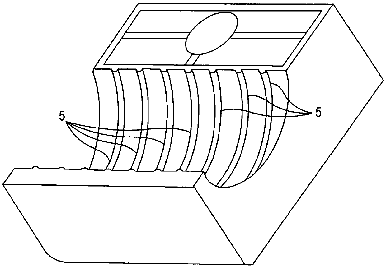
The claimed hanger may be used to support a variety of types and sizes of transmission lines including corrugated coaxial cable transmission line having a variety of cross sectional shapes. For the purposes of illustration, the preferred embodiment of the present invention is shown in the drawings in conjunction with the preferred use, i.e., to support a corrugated coaxial cable with a circular cross section.

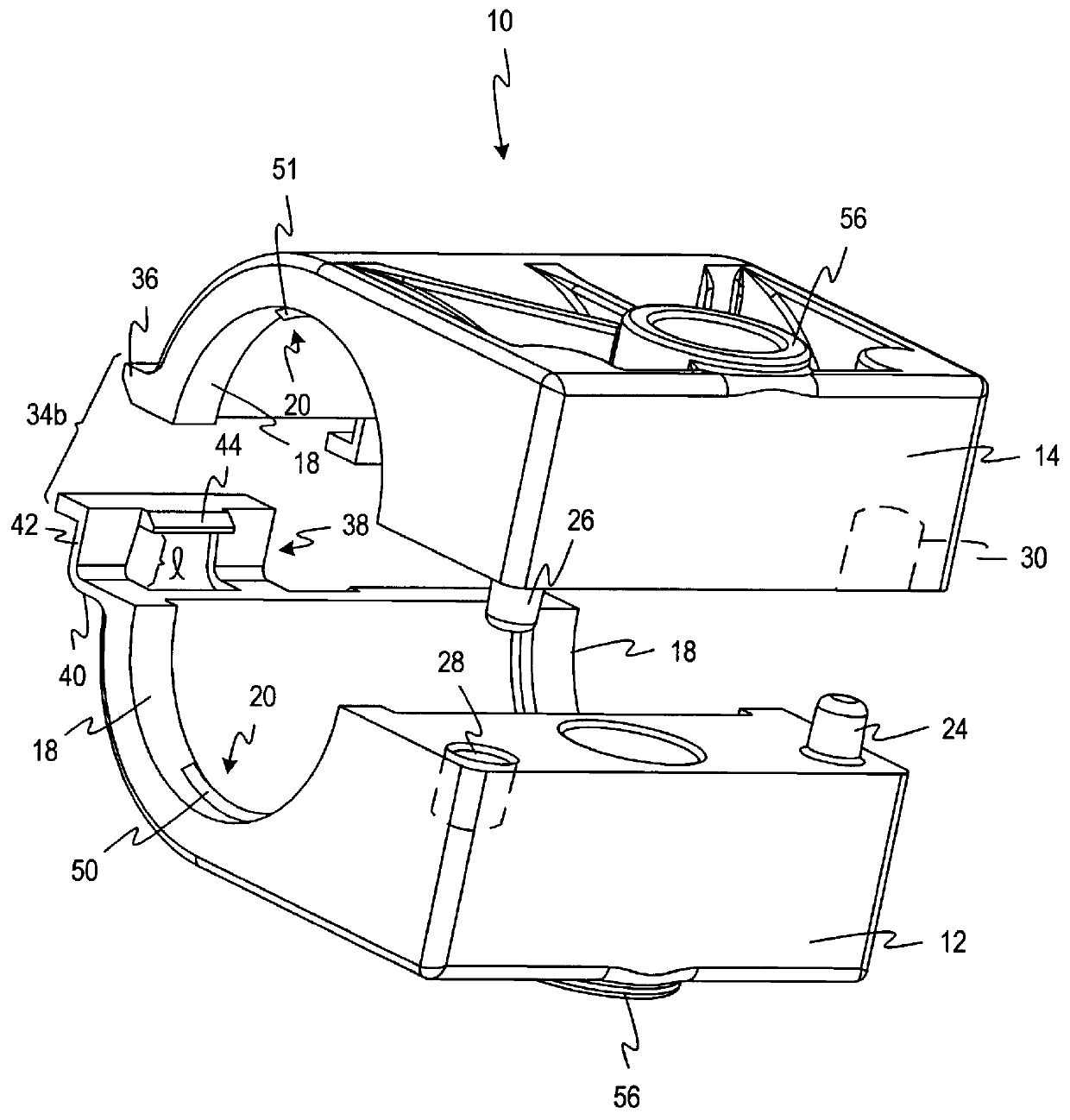
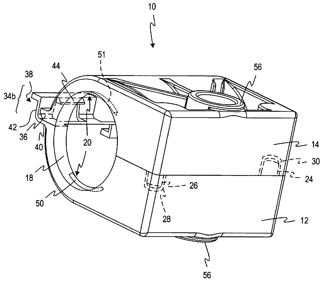
The present invention will now be described in connection with the drawings. FIGS. 2-5 illustrate a hanger 10 that includes a first section 12 and a second section 14 constructed in accordance with the present invention. In one embodiment, the sections 12 and 14 are structurally identical. The assembled hanger 10 has an inner generally cylindrical surface 18 having a circumference. Corrugated transmission lines have two diameters, an inner diameter measured between opposing recesses and an outer diameter measured between opposing crests. The generally cylindrical surface 18 is s...


PUM


Abstract

A transmission line hanger is provided for attaching a corrugated transmission line to a supporting structure. The hanger includes a first section adapted to engage a first side of the transmission line and a second section adapted to engage a second side of the transmission line. The first and second sections define an inner generally cylindrical the gripping ribs forms a protrusion extending radially inward from the inner generally cylindrical surface. The gripping ribs are spaced to fit into corresponding recesses in the corrugated outer surface of the transmission line. In another embodiment, the hanger further includes a snap clasp having two elements. The first element is a lip on the exterior of the hanger. The second element is a latch having three sides. In still another embodiment, the hanger includes a first alignment pin and a first mating recess on the fist section and a second alignment pin and a second mating recess on the second section. The first recess being adapted to receive the second alignment pin and the first alignment pin being adapted to fit in the second mating recess to align the first section with the second section.

Description

This invention relates generally to transmission lines, such as, corrugated coaxial cables, and in particular to transmission line hangers for supporting corrugated transmission lines used in antenna systems.Transmission line hangers are used to support transmission lines. In most uses, transmission lines are attached to a plurality of supporting structures along most of their lengths by a plurality of transmission line hangers. The most extensive use of hangers is in connection with coaxial cables, such as those disclosed in U.S. Pat. No. 5,334,051 (Devine et al.) and U.S. Pat. No. 5,167,533 (Rauwolf). Coaxial cables are extensively used for carrying electromagnetic signals.Transmission line hangers are used for supporting coaxial cables mounted on tall towers and along horizontal bridges. Hanger failure presents both functional and safety issues of a very serious nature. A variety of mounting and support means for coaxial cables have been disclosed in the prior art. For example, U...

Claims


Application Information

Patent Timeline
Patent Type & Authority Patents(United States)
IPC IPC(8): F16L3/10
CPCF16L3/1041
Inventor COX, ALBERT R.
Owner COMMSCOPE TECH LLC
Why Eureka
Try Eureka