Vehicle communication system for toll collection

a technology for vehicle communication and toll collection, applied in the field of vehicle communication system, can solve the problems of limited number of antenna units which can be arranged, difficult application, and inability to provide a number of antenna units for covering a wide communication area

Inactive Publication Date: 2000-06-27
DENSO CORP
View PDF24 Cites 72 Cited by
  • Summary
  • Abstract
  • Description
  • Claims
  • Application Information

AI Technical Summary

Problems solved by technology

The above systems are designed for a single traffic lane and therefore have some difficulties in application to a typical load having multiple lanes where a wide communication area is set.
The construction therefore has a problem in that, taking a frequency band per antenna unit into consideration, the number of antenna units which can be arranged is limited if an available frequency band is limited.
The communication time per antenna unit is inversely proportional to the number of antenna units, and the number of antenna units which can be used is also limited when considering a substantial time required for communication processing and the frequency of communication occurrence for reliably accomplishing comm...

Method used


Image

  • Vehicle communication system for toll collection
  • Vehicle communication system for toll collection
  • Vehicle communication system for toll collection

Examples


first embodiment

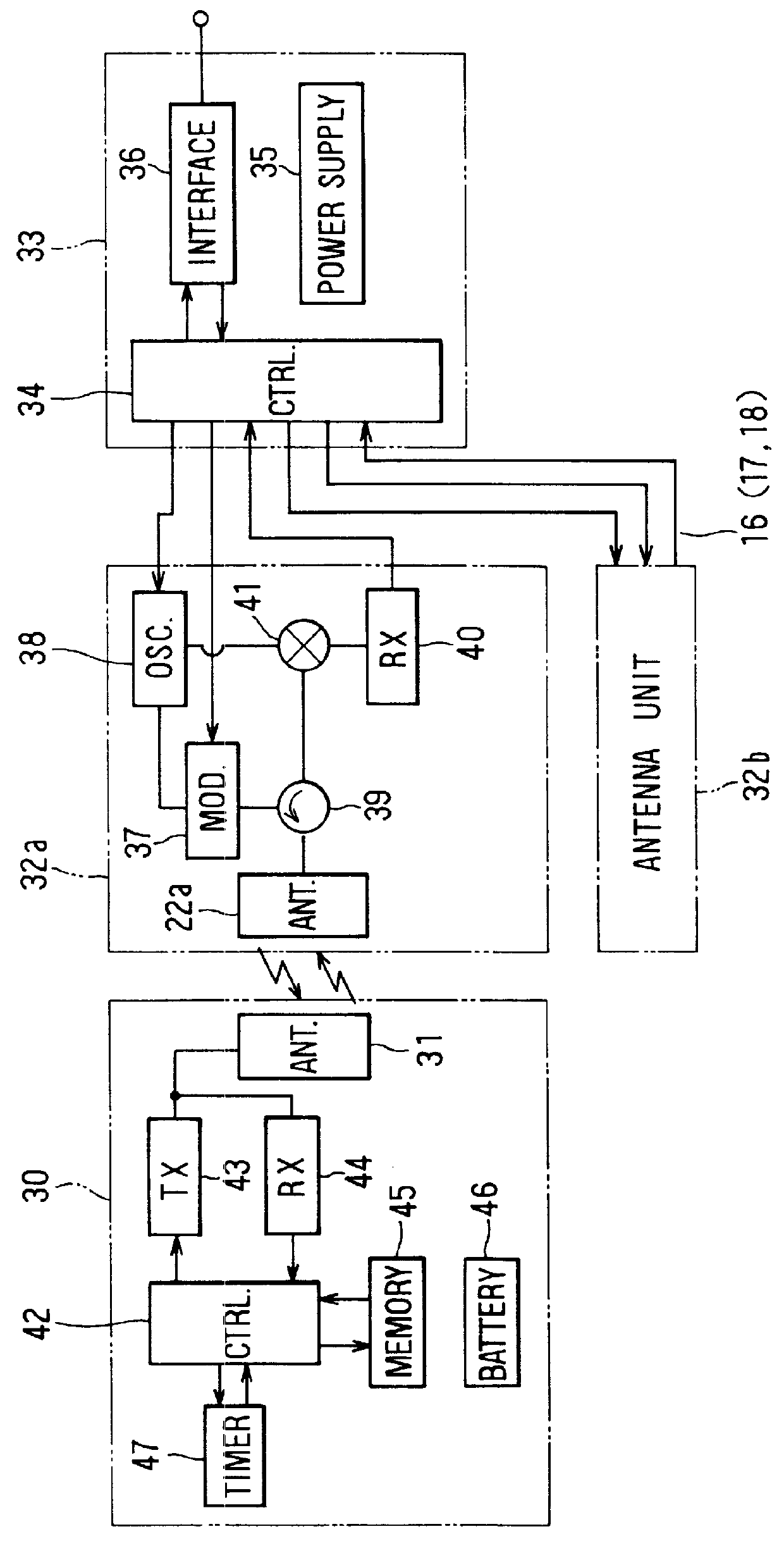
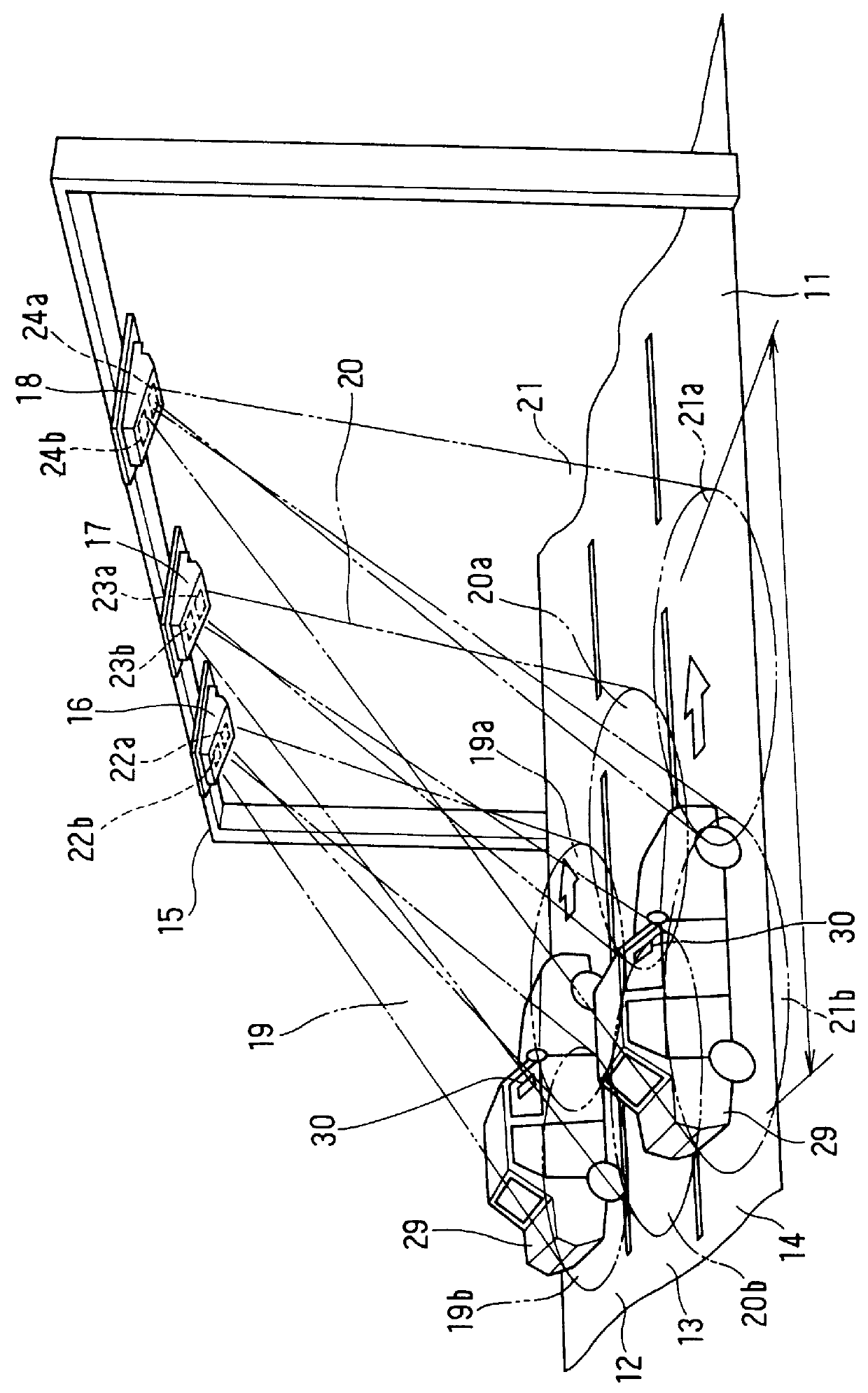
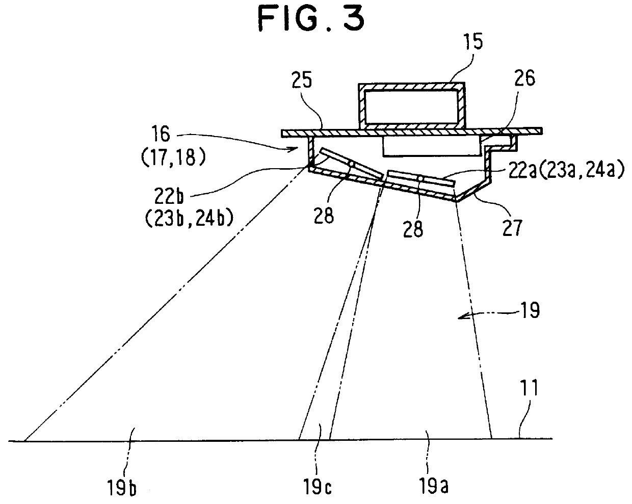
A first preferred embodiment in which the present invention is applied to a toll charging system for an expressway will be described hereinafter with reference to FIGS. 1-7D. In FIG. 2 showing an overall view of the first embodiment, an expressway 11 (only one direction of traffic flow of the expressway 11 is shown) has three lanes 12, 13 and 14 on one side. A predetermined toll charging point has a gantry 15 as a ground device extending over the road 11. The gantry 15 has antenna units 16-18 directed downward to corresponding ones of the lanes 12-14 to set communication areas 19-21.

The communication areas 19-21 are set in such a direction from the respective antenna units 16-18 that they cover approaching vehicles (represented by automobiles 29). In this embodiment, the antenna units 16-18 respectively have antenna elements 22a and 22b, 23a and 23b, and 24a and 24b that respectively set communicative areas 19a and 19b, 20a and 20b, and 21a and 21b, thereby respectively forming the ...

second embodiment

the present invention is shown in FIGS. 8A-8E and 9. According to this embodiment, as shown in FIG. 9, the operating frequencies of the antenna elements 22a and 22b of the antenna units 16 and 18 are set to the same frequency f1, and the operating frequency of the antenna elements 22a and 22b of the antenna unit 17 is set to a frequency f2 which is different from f1; that is, each communication cycle of antenna units 16-18 is set to be shifted by half a cycle between the adjacent antenna units. This embodiment has a construction wherein the on-vehicle device can perform communications at either frequency f1 or f2 which is set to the antenna units 16-18.

The principle of this embodiment will be described for the case where five antenna units A-E are used as well as described with reference to FIGS. 4A-4E in the first embodiment. The first group of the antenna units A, C and E is set to have the frequency f1, and the second group of the antenna units B and D is set to have the frequenc...


PUM


Abstract

To perform communication speedily and reliably at an increased frequency of communication occurrence when providing multiple antenna units which are set to the same frequency, each of antenna units having a gantry in a tollgate is set such that adjacent antenna units having the same frequency alternately perform communications. Each communication period is set to have a down link period in which an interrogation signal is transmitted and an up link period in which an unmodulated carrier wave is transmitted while a response signal is received. Upon receiving a signal, an on-vehicle device generates a response signal by using a control circuit and transmits the signal by reflection, and fixes a communication party for further communications. The communication cycles of adjacent antenna units are shifted from each other, thereby avoiding interference. The down link periods and the up link periods coincide between the antenna units whose communication areas are apart from each other, thereby avoiding interference.

Description

1. Field of the InventionThe present invention relates to a vehicle communication system including a ground device having multiple antenna units for setting specified communication areas on a road, and an on-vehicle device mounted on a vehicle for communicating with the ground device when the vehicle passes through the communication area.2. Description of Related ArtAn automatic toll charging method for a toll road such as an expressway has been provided where a vehicle has an on-vehicle device which stores a pre-registered identification number or the like and is capable of transmitting it, and a ground device is installed at a place for toll charging on the road so that communication is performed between the ground device and the on-vehicle device when the vehicle passes through a communication area set by the ground device, and the ground device stores an indication that the vehicle having the registered identification number has passed through the area, thereby performing toll c...

Claims


Application Information

Patent Timeline
IPC IPC(8): G07B15/00
CPCG07B15/063
Inventor ANDO, TOSHIHIDEKATOH, TAISEI
Owner DENSO CORP
Why Eureka
Try Eureka