Trailer landing gear lifting apparatus

Inactive Publication Date: 2000-07-11
QUEST TRANSPORTATION PROD
View PDF18 Cites 26 Cited by
  • Summary
  • Abstract
  • Description
  • Claims
  • Application Information

AI Technical Summary

Benefits of technology

An advantage of the present invention is that it is sufficiently simple to be inexpensive enough such that it provides a viable alternative to hand cranking.
A further advantage of the present invention is that it is sufficiently simple to be inexpensive enough such that, if desired, a separate tool can be provided for each trailer and the tool can be left permanently attached to the trail

Problems solved by technology

As can be appreciated, raising and lowering the landing gear 10 using the manual crank handle 24 is both laborious and time consuming.
However, the fact that the old fashioned hand crank still predominates i

Method used


Image

  • Trailer landing gear lifting apparatus
  • Trailer landing gear lifting apparatus
  • Trailer landing gear lifting apparatus

Examples


Embodiment Construction

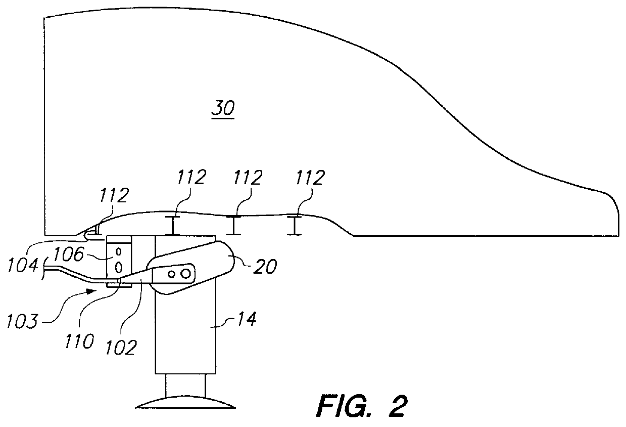
The best presently known mode for carrying out the invention is a trailer landing gear lifting apparatus adapted for raising and lowering the landing gear of semi trailers. The inventive trailer landing gear lifting apparatus is depicted in an elevational view in FIG. 2 affixed to the front end of a trailer 30 and is designated therein by the general reference character 100. The trailer landing gear lifting apparatus 100 has a pneumatic wrench 102, a fixture apparatus 103 having an attachment bracket 104 and a keeper arm 106. The wrench 102 has attached thereto an air hose 108 and a wrench bracket 110 which will be discussed in more detail, hereinafter.

The attachment bracket 104 is affixed to two of a plurality of I beams 112 which are a conventional appurtenances of the trailer 30. FIG. 3 is an exploded perspective view of the attachment bracket 104 in which it can be seen that the attachment bracket 104 has a long bracket 114 and a short bracket 116 which are fastened together by ...


PUM


Abstract

A trailer landing gear lifting apparatus (100) for raising and lowering landing gear (10) of a trailer (30) has a wrench (102) connected by an air hose (102, 222) to an air supply line ((212) and, optionally, to an air tank (210). An attachment bracket (104), a keeper arm (106) and a wrench bracket (110) optionally secure the wrench (102) to a pair of I beams (112) of the trailer (30) such that the wrench (102) is affixed to the trailer (30).

Description

The present invention relates to the field of pneumatically powered mechanical devices and more specifically to an improved pneumatic cranking device. The predominant current usage of the present inventive pneumatic landing gear lift is for raising and lowering the landing gear of semi trailers wherein it is desirable to provide a reliable and inexpensive alternative to hand cranking the landing gear.Trailers of tractor / trailer combinations have conventionally used landing gear, generally consisting of a pair of retractable legs, at the front ends of the trailers to support such front ends when the tractor is to be detached from the trailer. FIG. 1 depicts a conventional landing gear assembly 10. As can be seen in the view of FIG. 1, the landing gear 10 has a driven shaft 12 which passes through the upper ends of a pair of telescoping legs 14. Each leg 14 has an outer rectangular body 16 in which an inner rectangular portion 18 is telescopically received. Conventional gear mechanism...

Claims


Application Information

Patent Timeline
IPC IPC(8): B60S9/08B60S9/00
CPCB60S9/08
Inventor KINGSBURY, RICHARD A.
Owner QUEST TRANSPORTATION PROD
Why Eureka
Try Eureka