Combiner for power delivery over data communication cabling infrastructure

a data communication cabling and combinator technology, applied in data switching networks, data switching details, instruments, etc., can solve the problems of complicated installation, limited network elements, and increased cost, and achieve the effect of simplifying and reducing the cost of network element installation

Inactive Publication Date: 2005-08-04
CISCO TECH INC
View PDF42 Cites 16 Cited by
  • Summary
  • Abstract
  • Description
  • Claims
  • Application Information

AI Technical Summary

Benefits of technology

[0014] The present invention is a system for generating, delivering and distributing electrical power to network elements over a data communication network infrastructure within a building, campus or enterprise. Consolidating power distribution and data communications over a single network serves to (1) both simplify and reduce the cost of network element installation and (2) provide a means of supplying uninterrupted or backup power to critical network devices in the event of a power failure.
[0015] Network installations that utilize the present invention can be simplified and are less costly because the number of required power cables, power receptacles and AC power supplies or adapters is greatly reduced. In addition, network devices, terminals and other networking equipment can be placed without regard to the existence of or the location of AC receptacles.
[0016] The system of the present invention also provides for a significant cost reduction in providing uninterruptable backup electrical power to critical network devices and terminals in the event of a power supply failure or interruption. This is due to the fact that distributing backup power, i.e., power from an uninterruptable power supply, from a few points in the network via the LAN infrastructure is far more efficient than connecting each critical network element to its own dedicated UPS or to a backed up power line. An assumption that is valid most of the time is that only a relatively small portion of the network elements, e.g., hubs, switches, routers, etc., need to be connected to a dedicated source of uninterruptable power while the remainder of the critical network devices receive their operating power via the LAN infrastructure.
[0017] Another benefit of the system of the present invention is that the safety requirements and cost of network terminal equipment can be reduced since electrical power can now be fed from low voltages delivered over the LAN infrastructure. This is in contrast to the current method of providing an internal or external 110 / 220 VAC power supply that requires that the network device receive certification by one or more testing organizations such as Underwriters Laboratory (UL). In the case of IP telephony, which is becoming more and more popular, providing power over the LAN permits the IP telephone to have a source of uninterruptable power just as ordinary analog based telephones connected to the PSTN enjoy today.

Problems solved by technology

The requirement of network devices to connect to a source of electrical power complicates installation and makes it more costly.
In addition, it limits the location of network elements to locations where electrical power connections and data network connections are available.
Depending on the application, such as with IP or LAN telephones, the number of network devices that must operate during building power failures may be very high.
It is important to point out that the data communications network infrastructure was primarily designed and optimized to carry high bandwidth low power data communications signals and was not designed to deliver electrical power.
Thus, the cables, connectors, line interface circuitry and terminal devices are not designed to handle high levels of electrical power.

Method used


Image

  • Combiner for power delivery over data communication cabling infrastructure
  • Combiner for power delivery over data communication cabling infrastructure
  • Combiner for power delivery over data communication cabling infrastructure

Examples


Embodiment Construction

Notation Used Throughout

[0035] The following notation is used throughout this document.

TermDefinitionACAlternating CurrentBERBit Error RateDCDirect CurrentHDSLHigh bit rate Digital Subscriber LoopIPInternet ProtocolISDNIntegrated Service Digital NetworkLANLocal Area NetworkNICNetwork Interface CardPCPersonal ComputerPSTNPublic Switched Telephone NetworkULUnderwriters LaboratoryUPSUninterruptable Power SupplyWANWide Area Network

General Description

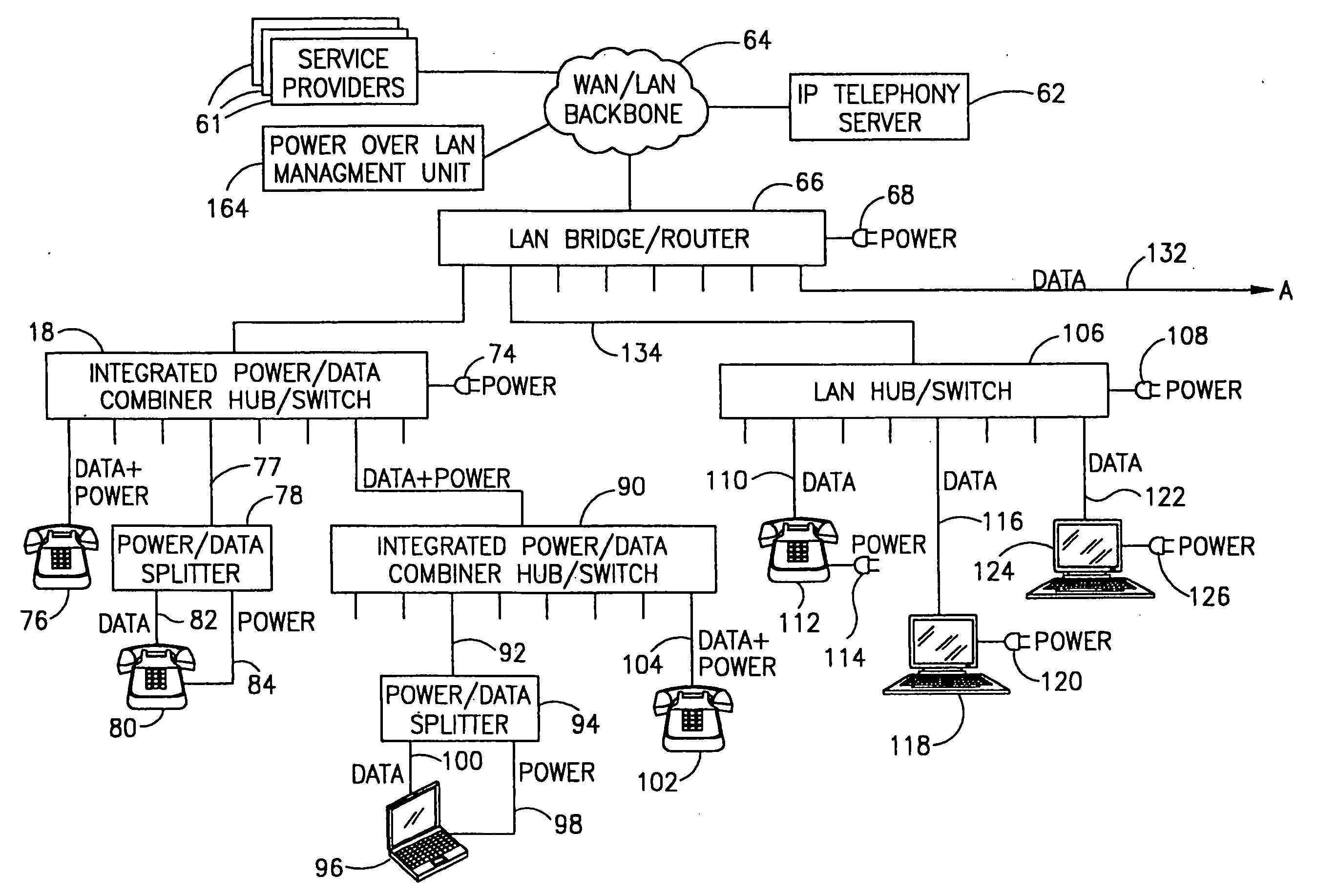
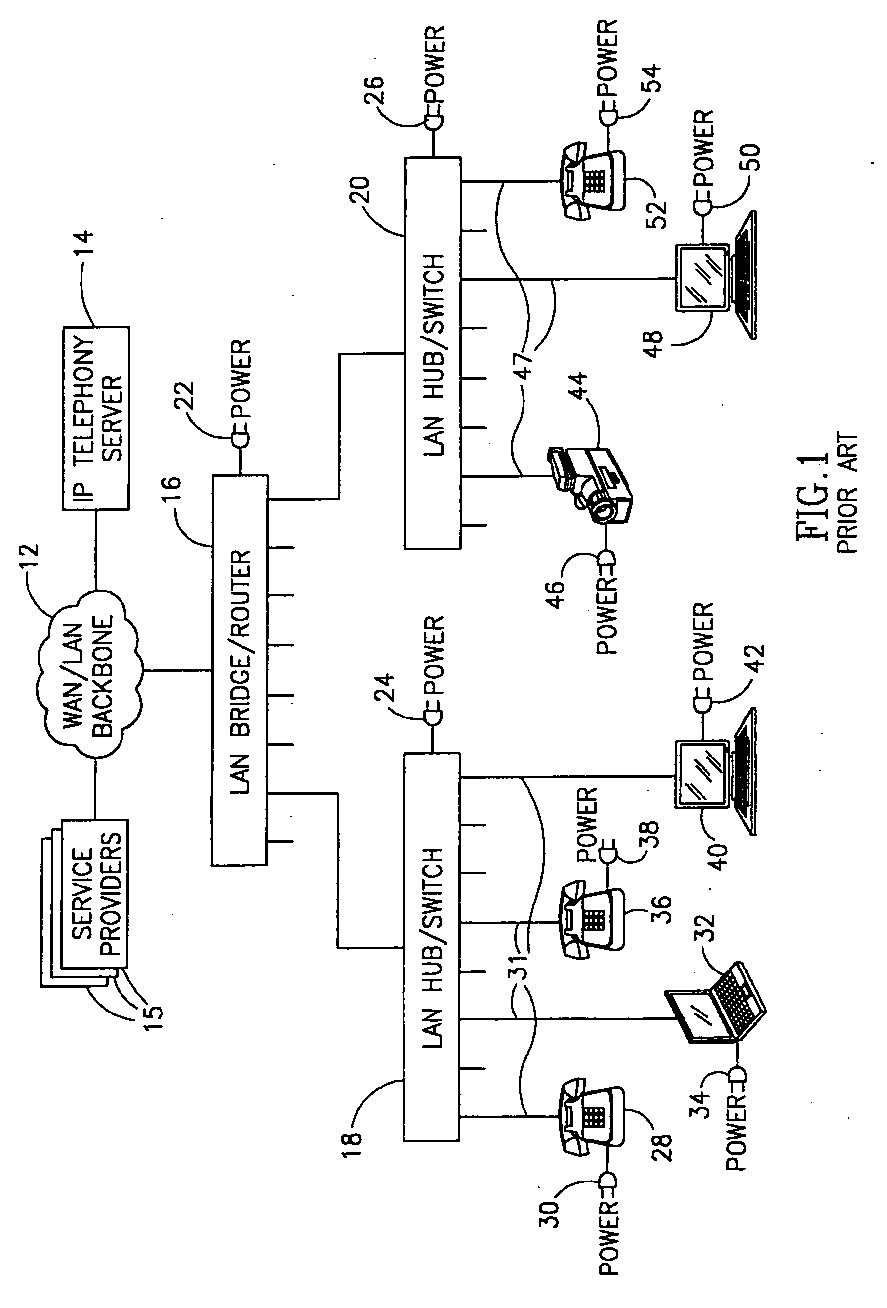
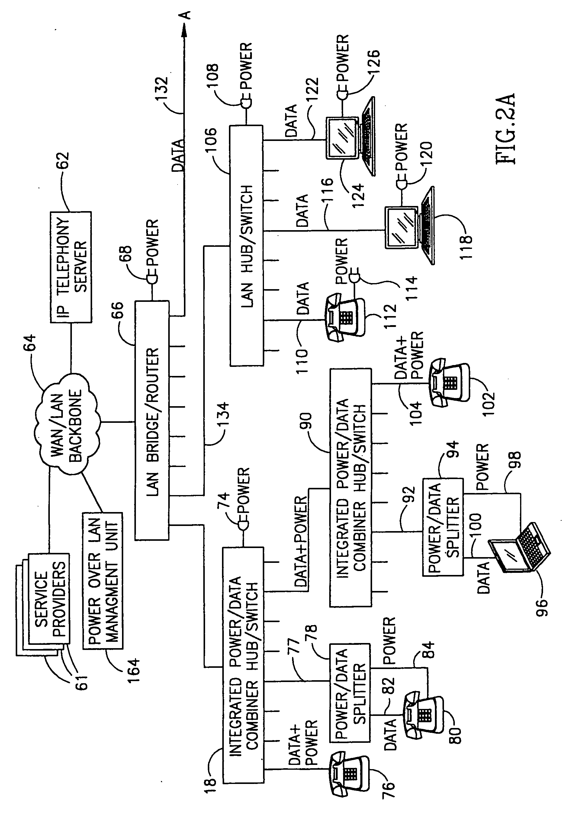
[0036] The present invention is a system for generating, delivering and distributing electrical power to network elements over a data communication network infrastructure within a building, campus or enterprise. Consolidating power distribution and data communications over a single network serves to simplify and reduce the cost of network element installation and to provide a means of supplying uninterrupted or backup electrical power to critical network devices in the event of a power failure.

[0037] The disclosure presented hereinbelow...


PUM


Abstract

A system for generating, delivering and distributing electrical power to network elements over a data communication network infrastructure within a building, campus or enterprise. Consolidating power distribution and data communications over a single network simplifies and reduces the cost of network element installation and provides a means of supplying uninterrupted or backup power to critical network devices in the event of a power failure. The invention includes power / data combiners that combine a data communication signal with a low frequency power signal. The combined signal is transported over the LAN infrastructure where a power / data splitter extracts the data signal and the power signal and generates two separate outputs. The power over LAN system of the present invention operates with high bandwidth data communication networks, i.e., 10 Mbps, 100 Mbps, 1000 Mbps. The electrical power distributed over the LAN can be delivered as DC or low frequency AC voltages which in either case will not interfere with data communications signals. The electrical power delivered over data communications cable can be transmitted using one or more spare pairs in the cable or over the receive and transmit wires.

Description

REFERENCE TO RELATED APPLICATIONS [0001] This application claims priority from U.S. Provisional Application Ser. No. 60 / 115,628 filed Jan. 12, 1999.FIELD OF THE INVENTION [0002] The present invention relates generally to power generation and delivery and more particularly relates to a system for generating power and delivering it over the data communication cabling infrastructure within a facility. BACKGROUND OF THE INVENTION [0003] Currently, the infrastructure making up Ethernet Local Area Networks (LANs) and Wide Area Networks (WANs) is constructed to carry and distribute high bit rate data communication signals between network devices. The network devices or elements, may include, for example, hubs, switches, bridges, routers, interconnection equipment, various devices that are equipped with Network Interface Cards (NICs), data servers, desktop PCs, portable PCs and other various network equipment. What all these devices have in common, among other things, is that they all requi...

Claims


Application Information

Patent Timeline
Patent Type & Authority Applications(United States)
IPC IPC(8): G06F1/26H02GH02G3/00H04LH04L12/10H04L12/44H04L29/06H04L29/08
CPCG06F1/26H02G3/00H04L69/323H04L12/44H04L29/06H04L12/10H04L9/40
Inventor LEHR, AMIRATIAS, ILAN
Owner CISCO TECH INC
Why Eureka
Try Eureka