System for displaying images and/or information on aircraft blades and method thereof

a technology for aircraft blades and images, applied in projectors, instruments, computing, etc., can solve the problems of difficult communication between aircraft and ground crew, inability to determine the proper direction of travel, and often disorientation of ropes from helicopters, etc., to minimize or eliminate the

Inactive Publication Date: 2012-04-17
US SEC THE ARMY THE
View PDF21 Cites 15 Cited by
  • Summary
  • Abstract
  • Description
  • Claims
  • Application Information

AI Technical Summary

Benefits of technology

[0013]If there are no restrictions on projecting laser light upwards past the spinning blades, this invention is simplified by not restricting light or laser emissions to only illuminating the blades and the laser light can be projected into the air beyond the blades, minimizing or eliminating the need to pulse the laser light source in synchronism with the blade(s). Thus, the laser light could be projected between the blade(s) onto the clouds or smoke above the helicopter, or into the open air.

Problems solved by technology

Each main rotor blade is connected to the shaft by a flexible hinge, allowing the rotor blades to rise and fall slightly as they rotate, resulting in flapping.
For example, rescue helicopters rescuing water bound persons may need to give instructions to the person floating in the water below, when speaker projection systems may be insufficient in producing sufficient signal to noise ratios to overcome the helicopter and surf noise
However, soldiers that fast-rope from a helicopter are often disoriented during the insertion process, and unable to determine the proper direction of travel on reaching the ground.
Although radio communication is sometime used to assist the ground personnel, radios are not issued to every ground soldier, and often the communication between aircraft and ground crew is difficult due to environment and operational distractions.

Method used


Image

  • System for displaying images and/or information on aircraft blades and method thereof
  • System for displaying images and/or information on aircraft blades and method thereof
  • System for displaying images and/or information on aircraft blades and method thereof

Examples


Embodiment Construction

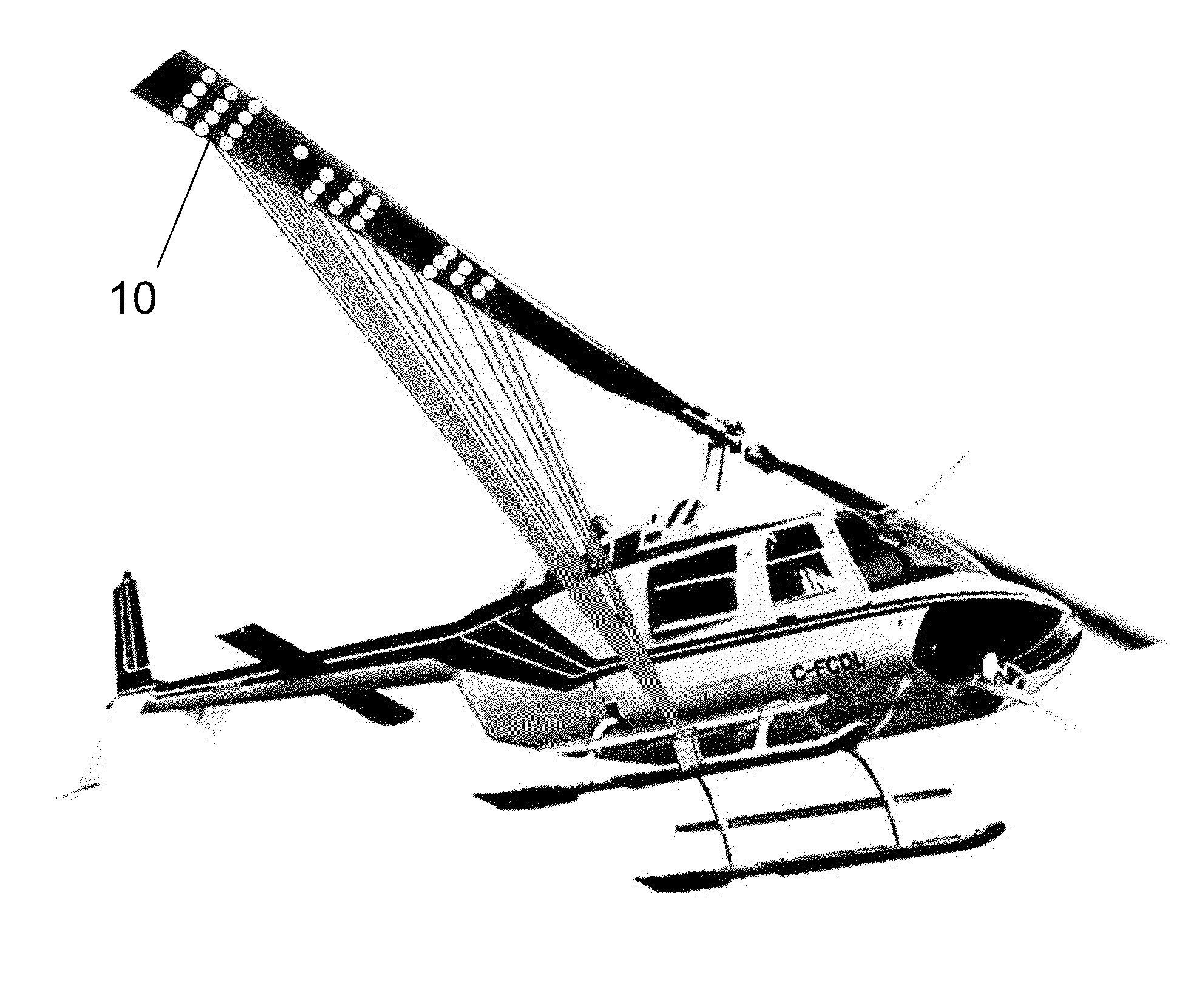
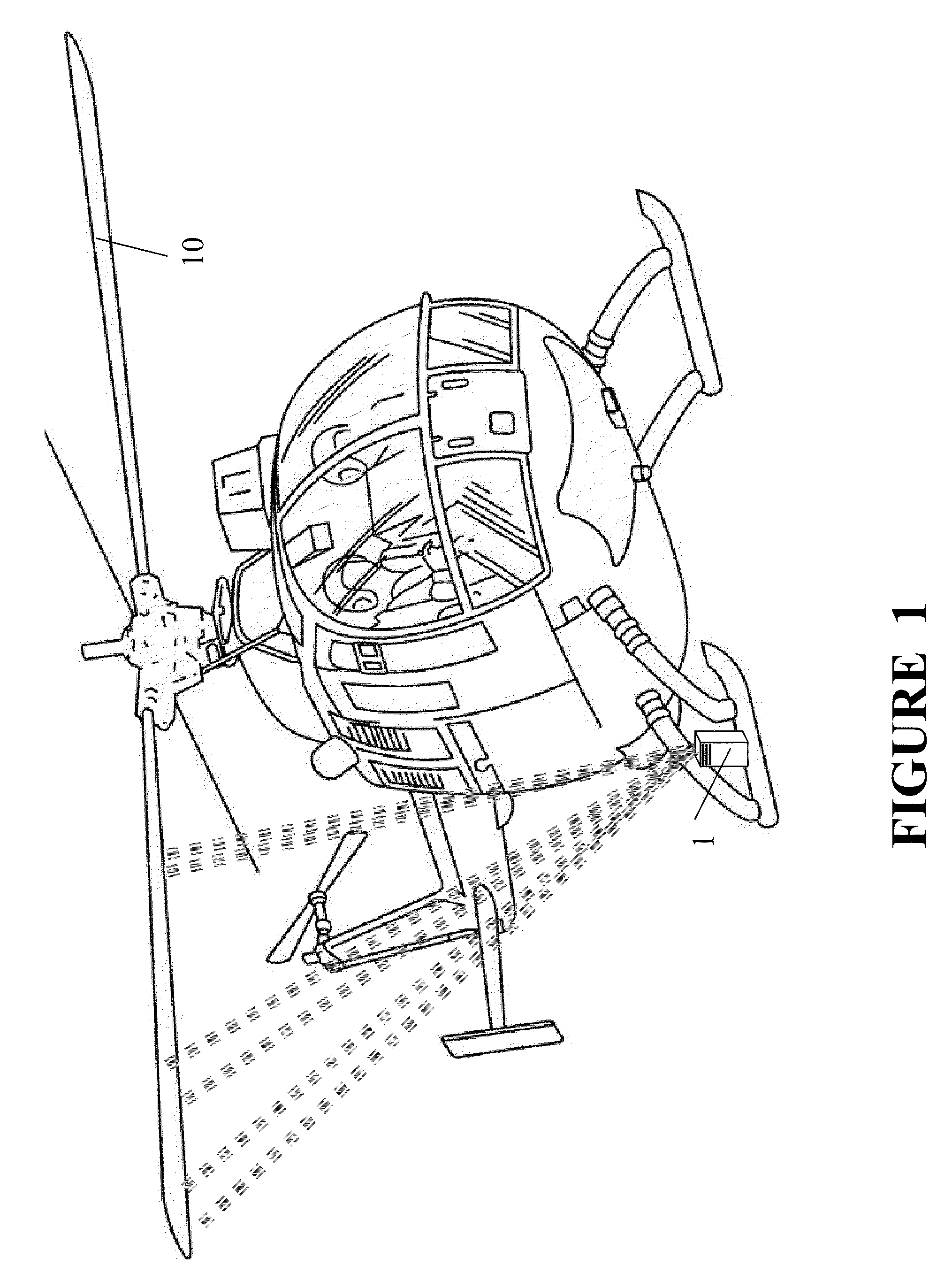
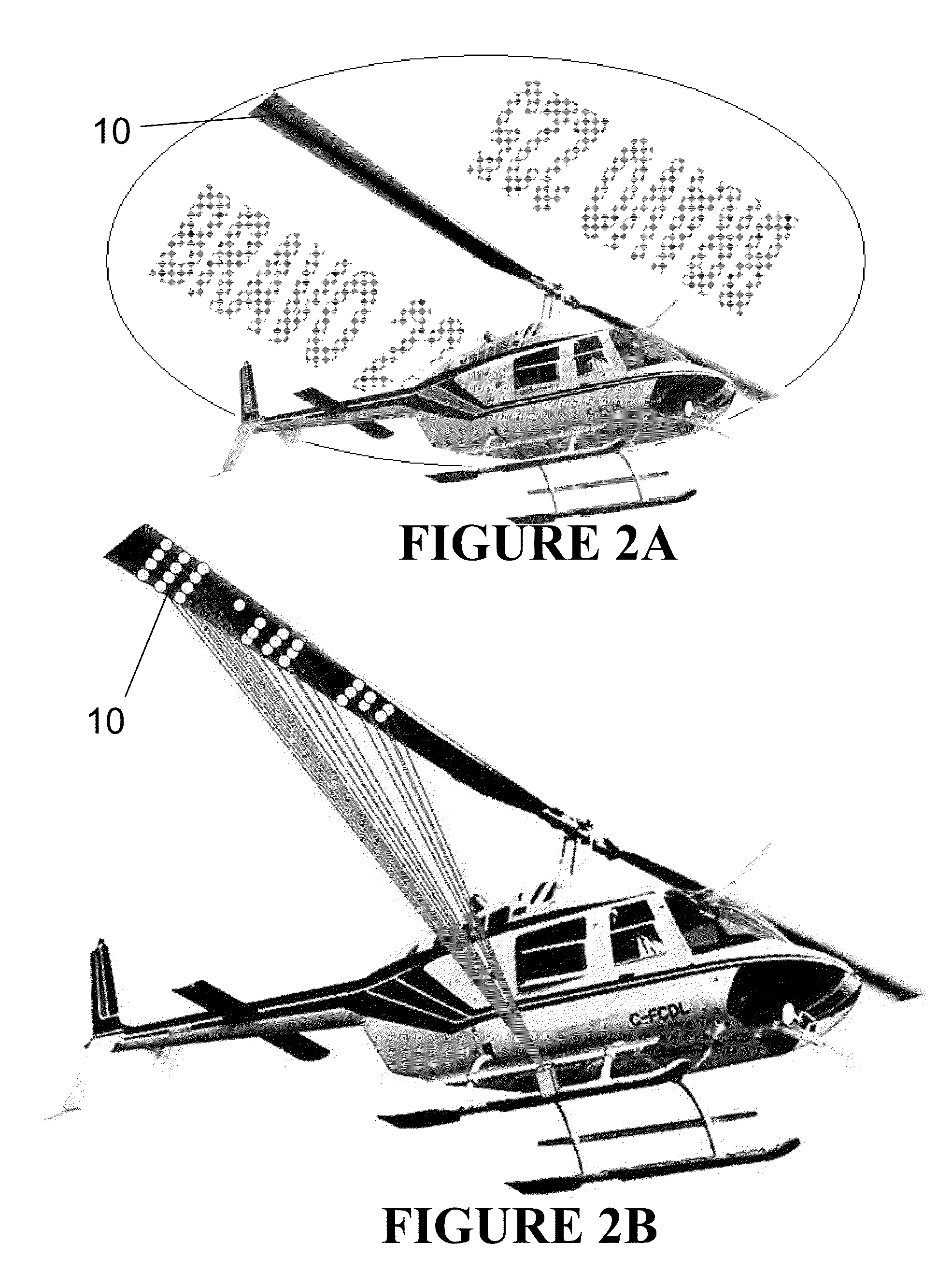
[0039]As illustrated in FIGS. 1 and 3, the present invention provides a system capable of projecting laser images on the underside of the helicopter rotor, and a method comprising same. In practice, a laser image is projected onto a helicopter's rotor, which may comprise one or more blades 10. As the blades spin, due to “persistency of the human eye,” the human brain will perceive the image still to be there for a short time after blade has moved. The human eye spatially and temporally scans the laser images that are being projected onto the moving blades, resulting in a full image retention or visualization.

[0040]As shown in FIG. 3, the position of the blade 10 is sensed by the blade position sensor 21 which transmits a signal to the synchronizing device 17. Light passing from the laser array is synchronized by the synchronizing device 17 operatively connected to the blade position sensor so that light will be emitted during a specific time interval. The image to be projected is st...


PUM


Abstract

A system for displaying information via a light source on rotating helicopter blades of an aircraft such as a helicopter is provided. The light source may be a laser light source and the light therefrom may be directed onto the aircraft blade by one or more motion controlled mirrors and a computer controller. A sensor is capable of determining the position of helicopter blades during rotation, such that light may be projected upon only the moving blade at precisely timed intervals, so as to form perceivable graphics and / or messages thereon. In addition, such system may be utilized for displaying graphics and / or messages on rotating propellers of fixed wing aircraft.

Description

STATEMENT OF GOVERNMENT INTEREST[0001]The invention described herein may be manufactured, used, imported, sold, and licensed by or for the Government of the United States of America without the payment or any royalty thereon or thereforeFIELD OF THE INVENTION[0002]The present invention provides a system for displaying information on the underside of rotating blades via lasers. In particular, a system is provided, comprised of a light source(s) for illumination of at least one rotating blade by a computer controller, which is capable of determining the position of the rotating blade during rotation, and displaying laser light upon the moving blade at precisely timed intervals, so as to form perceivable graphics and / or messages thereon. In addition, such a system is provided for displaying graphics and / or messages on the external surfaces of marine vessels, aircraft, etc.BACKGROUND OF THE INVENTION[0003]The display of messages and indicia on a fan is disclosed in U.S. Pat. No. 7,161,2...

Claims


Application Information

Patent Timeline
Patent Type & Authority Patents(United States)
IPC IPC(8): G03B21/00G06F3/038G03B21/56
CPCG03B21/00
Inventor SCANLON, MICHAEL V.
Owner US SEC THE ARMY THE
Why Eureka
Try Eureka