Print ribbon feeder and detection system

a detection system and ribbon technology, applied in the field of printers, can solve the problems of not being able to effect the loading of the strip, affecting the loading speed of the strip,

Inactive Publication Date: 2000-07-18
PRINTRONIX LLC
View PDF19 Cites 41 Cited by
  • Summary
  • Abstract
  • Description
  • Claims
  • Application Information

AI Technical Summary

Benefits of technology

Consequently, this invention allows for emplacement of the ribbon without further action and while at the same time automatically providing for orientation and driving of the ribbon in the right direction from the substantially full spool to the take-up spool.

Problems solved by technology

A major problem with regard to loading the inked ribbon into a printer is the fact that the ribbon itself has ink which can be imparted to any surface which it touches.
When handling the ribbon, users often times find their hands very dirty as well as various portions of the equipment.
In the past, it has been a significant problem to load an inked ribbon without getting dirty.
However, there has been no ability to effect the loading of the strip and have a fail safe means of recognizing the position of where the clean strip is in comparison to the inked ribbon.

Method used


Image

  • Print ribbon feeder and detection system
  • Print ribbon feeder and detection system
  • Print ribbon feeder and detection system

Examples


Embodiment Construction

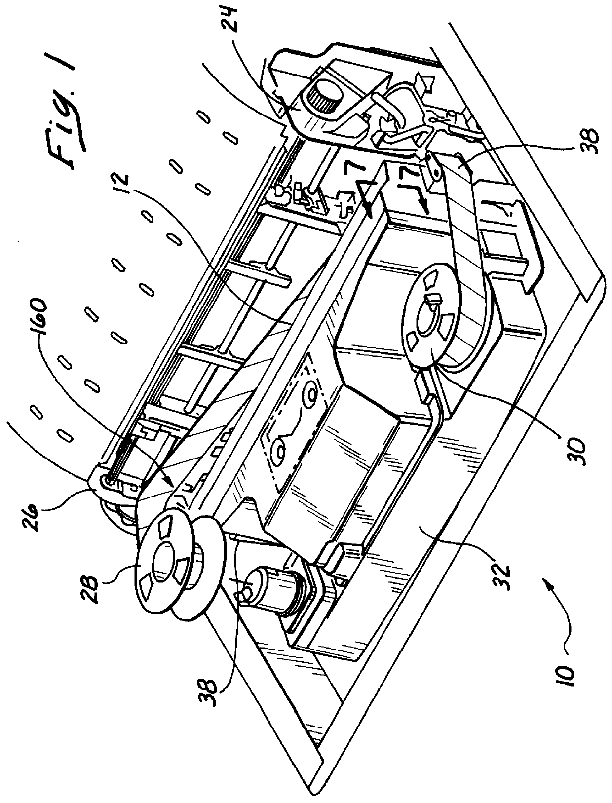
FIG. 1 shows a printer 10 of the type known as a dot matrix line printer. A ribbon is shown being emplaced in the printer attached to two spools which will be detailed hereinafter.

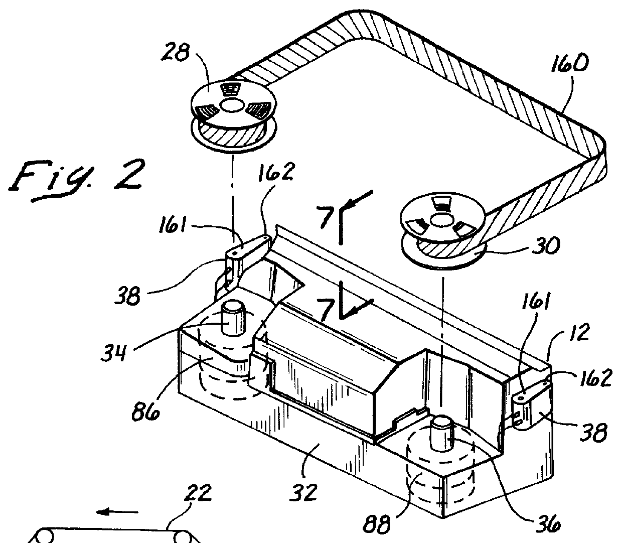
The printer includes an elongated hammerbank 12 hidden from view. The hammerbank 12 is mounted and driven in a reciprocating manner by a shuttle drive. The hammerbank reciprocates with respect to a platen 16 as seen in FIG. 7 sectioned from lines 7--7 of FIGS. 1 and 2. The space between the hammerbank 12 and the platen 16 defines a print station 18. This is more easily seen in FIG. 7.

Looking more particularly at FIG. 7, it can be seen that within the print station 18 is a length of print paper 20 and a print ribbon 22.

The print paper 20 is advanced upwardly through the print station 18 by two tractor drives 24 and 26 on opposite sides of the printer. The tractor drives 24 and 26 move the paper 20 upwardly as each row of dots is printed thereacross.

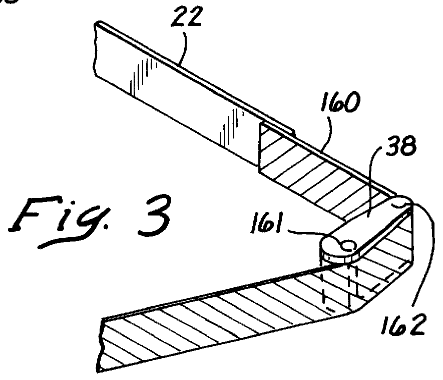
The ribbon 22 extends along the length of the print station...


PUM


Abstract

A clean print ribbon feed system and method for a printer having a ribbon with two non-inked clean hands portions wound around a pair of spools is disclosed. Detection of the spool having greater angular velocity and lesser angular velocity determines the direction of feed. The spool having greater angular velocity winds and takes up the print ribbon. The non-inked portion can be formed as a conductive plastic and is initially wound on each spool. Detection of the non-inked portion of the ribbon takes place by two electrical contactors. The determination of the angular velocity of the spools determines the amount of print ribbon on one of the spools so that the spool having the lesser ribbon can be driven as a take-up spool to provide proper directional drive for winding the clean hands portion and the inked portion which follows.

Description

FIELD OF THE INVENTIONThe field of this invention pertains to printers and particularly those printers that have ribbons that are impacted for printing on paper or other media. In such printers, it is known to drive a ribbon from two spools. Generally, one end of the ribbon is connected to a spool driven by a motor in a winding or take-up mode. The other portion of the ribbon is connected to a spool in a feed mode. This invention particularly relates to emplacing the ribbon with a clean non-inked leader or portion and then appropriately driving it.BACKGROUND OF THE INVENTIONThis invention is particularly adapted to ribbon drives for impact printers. Such impact printers can be dot matrix printers and more specifically line type printers. Such line printers are known in the art and have been developed extensively by the assignee of this invention.The inked ribbons of such various printers are repeatedly impacted against a length of print paper or other printable medium by certain imp...

Claims


Application Information

Patent Timeline
Patent Type & Authority Patents(United States)
IPC IPC(8): B41J33/14B41J33/36B41J31/05B41J33/16B41J33/32B41J33/52B41J35/36
CPCB41J33/14B41J33/36
Inventor BARRUS, GORDON B.ANDERSON, GREG J.
Owner PRINTRONIX LLC
Why Eureka
Try Eureka