The present invention relates to dampening devices and methods that dampen the retraction velocity of needles used in connection with semi-automatic needle retracting
vascular access devices. These devices prevent splattering or dripping of blood during needle retraction. In addition, the dampening devices of the present invention can be modified to regulate the amount of dampening and can be retrofit to existing
vascular access devices.
In one embodiment, a needle retracting safety vascular access device comprises a housing having a housing cavity. An introducer needle is positioned with its proximal end residing outside the housing and its distal end disposed within the housing cavity. As used herein, the term proximal means the end of the device furthest from the practitioner, and the term distal means the portion of the device closest to the practitioner. The introducer needle is placed in communication with a hub which holds the needle in place during
insertion and retraction. The hub, in turn, is in communication with a spring retraction mechanism. A dampening device comprising a collapsible bladder is disposed within the housing cavity and positioned at the distal end of the needle. The distal end of the bladder has a bladder vent which allows
ambient air in the bladder to exit. As the needle begins to retract into the housing cavity, the needle contacts the bladder which is filled with
ambient air. The
ambient air filled bladder dampens the velocity of the needle. Air is expelled through the bladder vent in a controlled manner by the pressure of the spring, thus allowing the needle to likewise retract in a controlled fashion.
In a second embodiment, a needle retracting safety vascular access device comprises a housing having a housing cavity. An introducer needle is positioned with its proximal end residing outside the housing and its distal end disposed within the housing cavity. The introducer needle is placed in communication with a hub which holds the needle in place during
insertion and retraction. The hub, in turn, is in communication with a spring retraction mechanism. A dampening device comprising a
piston is disposed within the housing cavity near the distal end of the needle. The
piston is in communication with the needle so that it retracts concurrently with the needle during retraction. The
piston has at least one wiping
flange configured around the piston. The wiping
flange creates a seal between the piston and the housing cavity. The housing additionally has at least one longitudinal vent groove carved into the housing cavity. As the needle and the piston move distally through the housing cavity during retraction, ambient air in the housing cavity is compressed by the piston thereby dampening the velocity of the needle. Air is expelled in a controlled manner through the longitudinal vent groove by the pressure of the spring, thus allowing the needle to likewise retract in a controlled fashion.
In a third embodiment, once again a needle retracting safety vascular access device comprises a housing having a housing cavity. The distal end of the housing also has a housing vent. An introducer needle is positioned with its proximal end residing outside the housing and its distal end disposed within the housing cavity. The introducer needle is placed in communication with a hub which holds the needle in place during
insertion and retraction. The hub, in turn, is in communication with a spring retraction mechanism. A dampening device comprising a piston is disposed within the housing cavity and positioned at the distal end of the needle. The piston is in communication with the needle so that it retracts concurrently with the needle during needle retraction. The piston comprises a circumferential groove. The circumferential groove is completely filled with a
viscous material so that it is in contact with the housing. As the needle and piston move distally during retraction, the resistance of the
viscous material against the housing dampens the velocity of the needle, thus allowing the needle to retract in a slow and controlled fashion.
Ambient air compressed during retraction is expelled out of the housing vent.
In a fourth embodiment, a needle retracting safety vascular access device comprises a housing having a housing cavity. An introducer needle is positioned with its proximal end residing outside the housing and its distal end disposed within the housing cavity. The distal end of the introducer needle has at least one needle
flange. The introducer needle is placed in communication with a hub which holds the needle in place during insertion and retraction. The hub, in turn, is in communication with a spring retraction mechanism. A dampening member is disposed within the housing cavity and positioned at the distal end of the needle. The dampening member comprises at least one track. Disposed within the track is a
viscous material, such as
silicone. As the needle move distally during retraction, the flange slides down the track of the dampening member. The resistance of the flange against the viscous material disposed within the track dampens the velocity of the needle, thus allowing the needle to retract in a slow and controlled fashion.
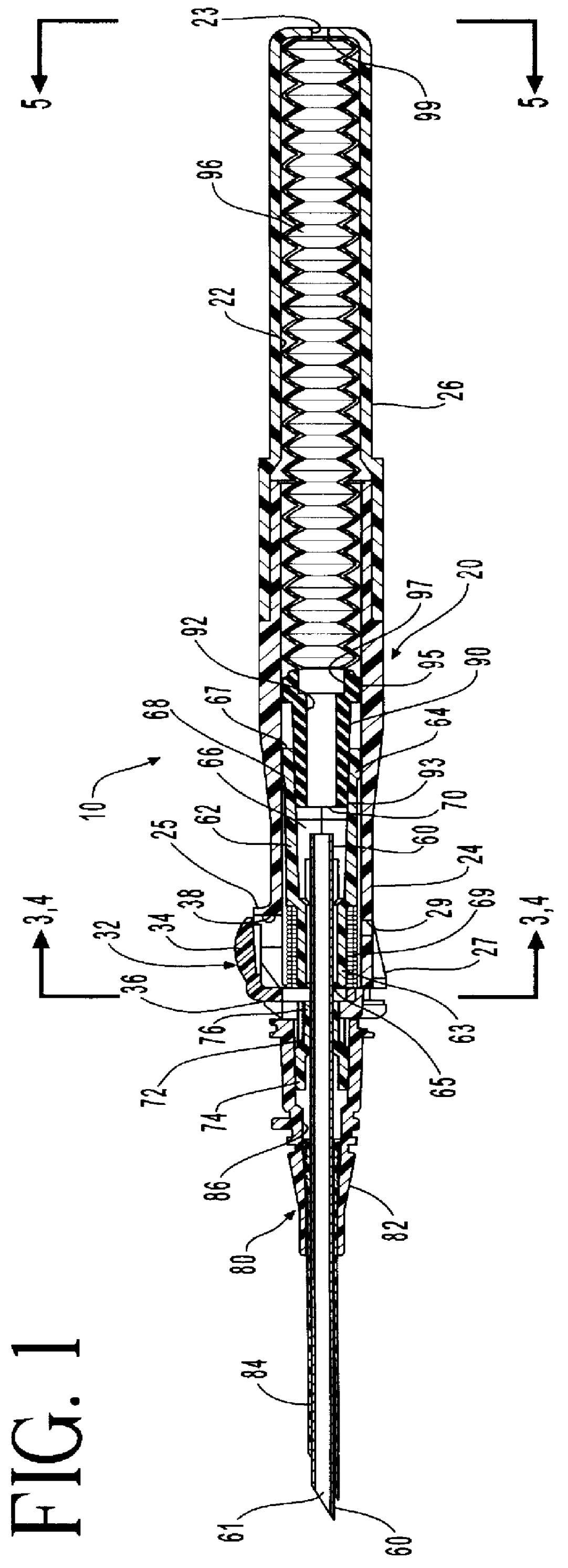
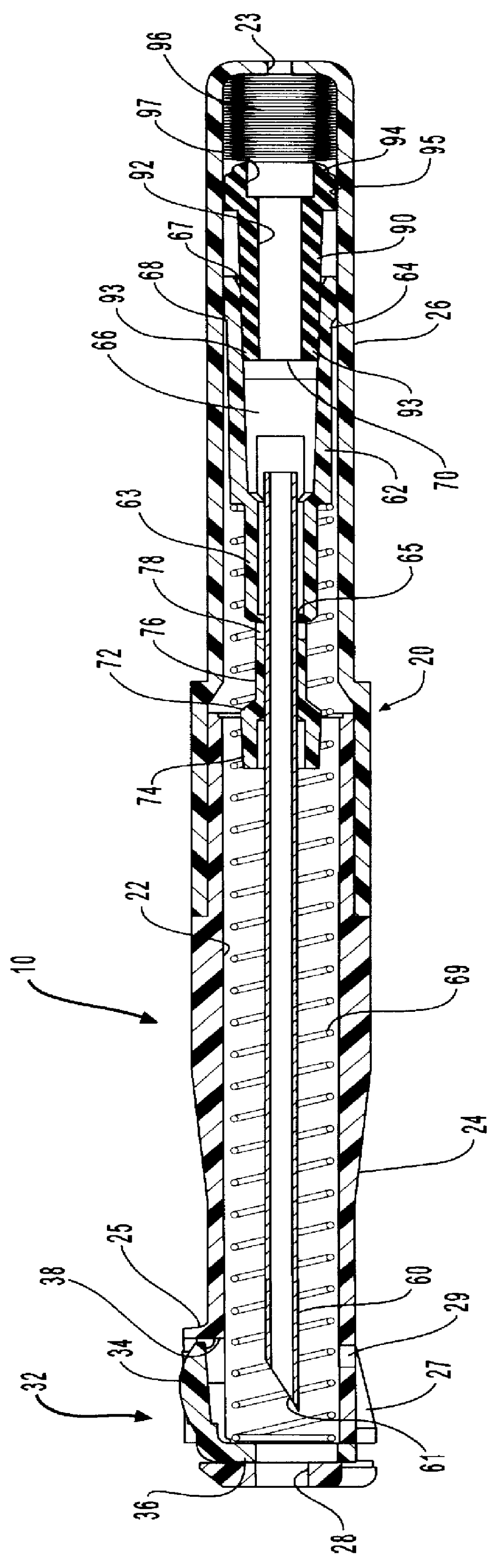
In fifth embodiment, a needle retracting safety vascular access device comprises a housing having a housing cavity. An introducer needle is positioned with its proximal end residing outside the housing and its distal end disposed within the housing cavity. The introducer needle is placed in communication with a hub which holds the needle in place during insertion and retraction. The hub, in turn, is in communication with a coiled spring retraction mechanism. Disposed within the housing cavity is at least one spring compression node positioned distally of the spring. The node reduces the
effective diameter of housing cavity. The spring compression node dampens the velocity of the needle by requiring that each individual coil radially contract before it can advance past the spring compression node and continue through the housing cavity. As each coil of the spring advances past the spring compression node, the hub, and hence introducer needle, is slowly urged distally until the introducer needle is completely within the housing cavity

