Safety device in lighting rods

a safety device and lighting rod technology, applied in lighting and heating apparatus, combustion process, burners, etc., can solve the problems of not knowing how to use lighting rods appropriately, unfavorable lighting rods, and the lik

Inactive Publication Date: 2000-07-25
TOKAI
View PDF12 Cites 65 Cited by
  • Summary
  • Abstract
  • Description
  • Claims
  • Application Information

AI Technical Summary

Benefits of technology

The primary object of the present invention is to provide a safety device, which is applied to a lighting rod for carrying out the lighting by an opera...

Problems solved by technology

However, with the lighting rods, persons, such as children, who do not know how to use the lighting rods appropriately, can light a fire carelessly.
Therefore, the lighting rods are not favorable from the viewpoint of safety.
With the conventional lighting rods described above, the problems occur in that, after the locking member has been moved to the position for the lock release and a fire has been lighted, if the user forgets to return th...

Method used


Image

  • Safety device in lighting rods
  • Safety device in lighting rods
  • Safety device in lighting rods

Examples


first embodiment

the safety device in a lighting rod in accordance with the present invention will be described hereinbelow.

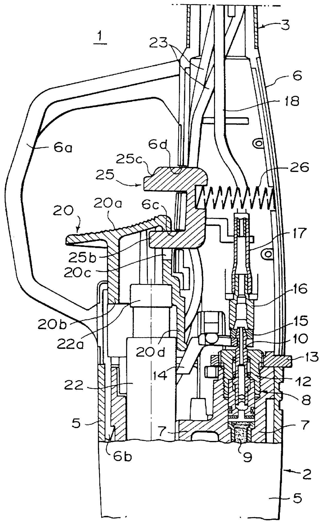
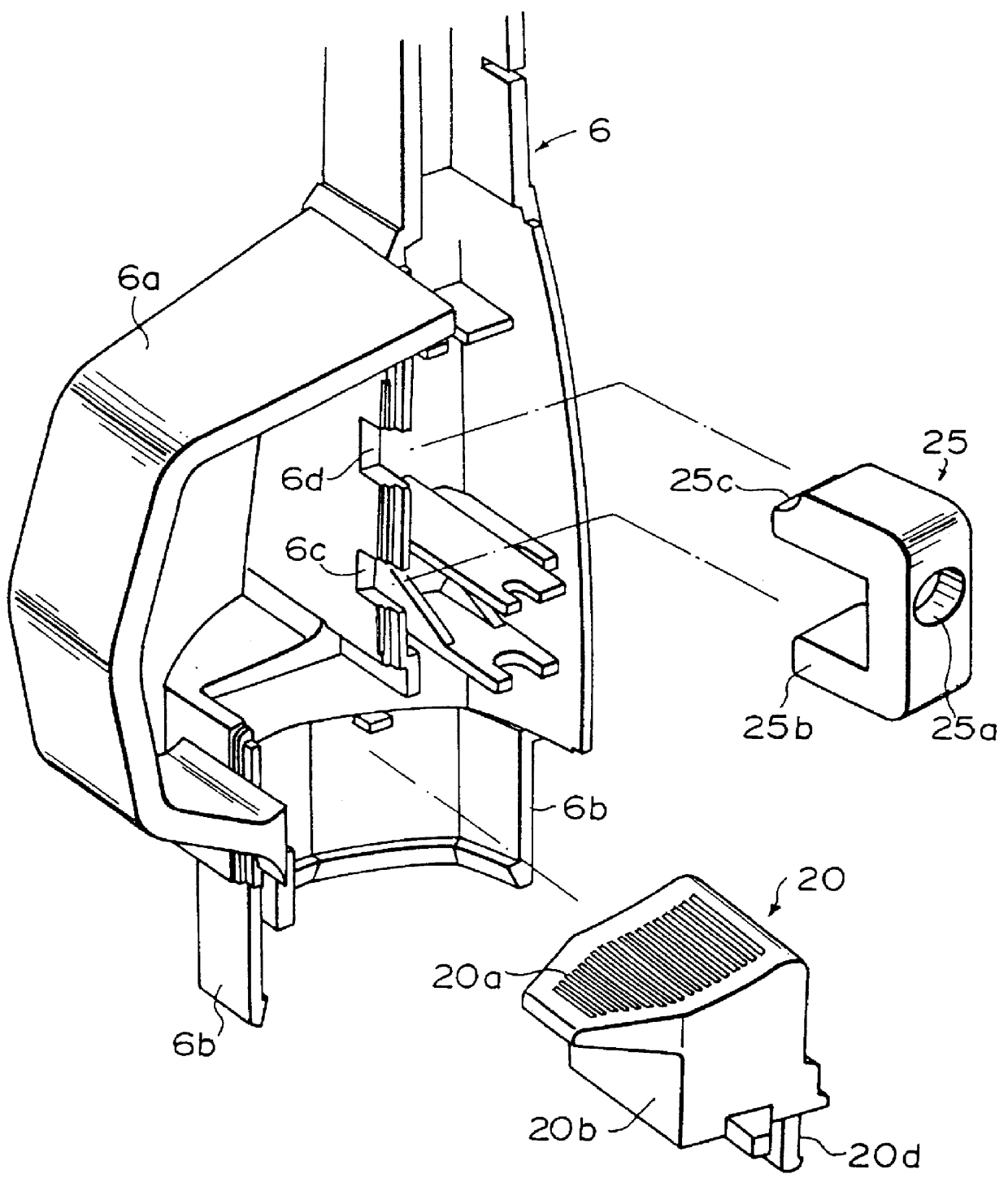
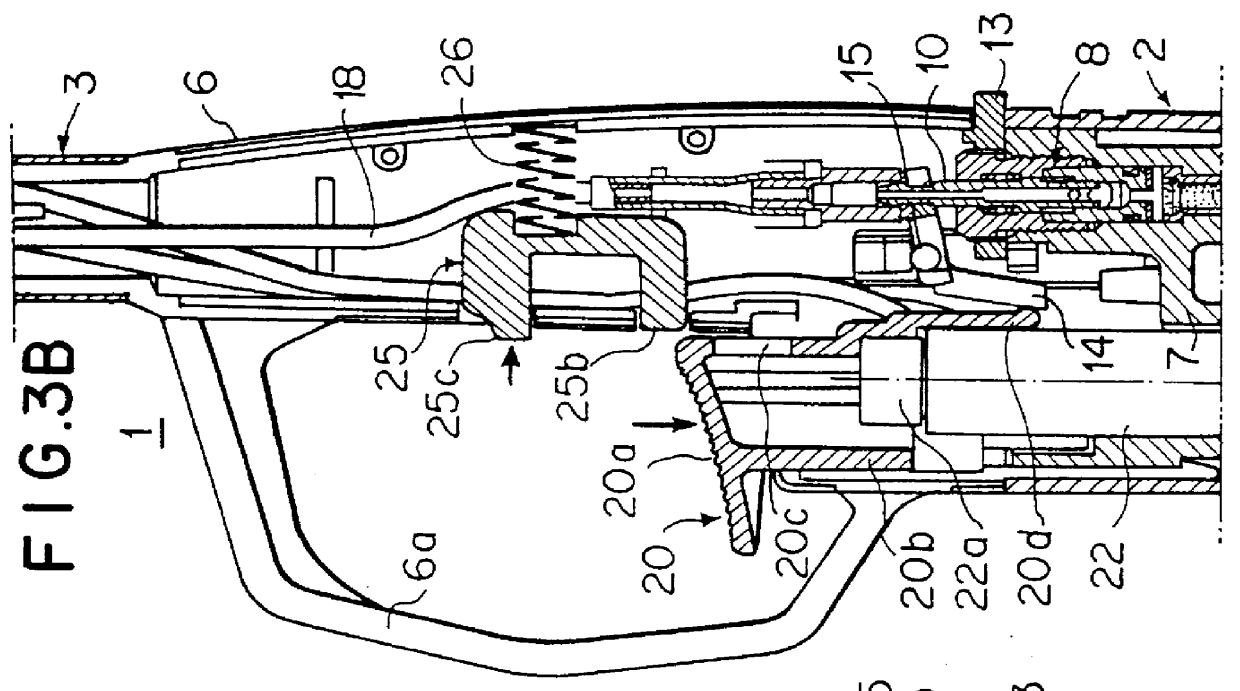
FIG. 1 is a vertical sectional side view showing the major part of a lighting rod, in which the first embodiment of the safety device in accordance with the present invention is employed. FIG. 2 is an exploded perspective view showing an intermediate case housing, an operation member, and a locking member in the first embodiment of FIG. 1. FIGS. 3A and 3B are sectional side views showing how the first embodiment of FIG. 1 operates.

A lighting rod 1 comprises a main body 2 and an extension 3, which has a rod-like shape and extends from the main body 2. (A top end of the extension 3 is not shown in FIG. 1.) The case housing of the main body 2 is constituted of a tank cover 5, which is located on the base end side of the main body 2, and an intermediate case housing 6, which is located on the side forward from the tank cover 5 (i.e., on the upper end side of the main body 2 in FIG....

second embodiment

the safety device in a lighting rod in accordance with the present invention will be described hereinbelow.

FIGS. 4A and 4B are sectional side views showing the major part of a lighting rod, in which the second embodiment of the safety device in accordance with the present invention is employed. In the second embodiment, a modified form of a locking member is employed. In this embodiment, the basic structures of the valve mechanism 8, the operation member 20, and the like, of the lighting rod 1 are identical with those in the first embodiment. In FIGS. 4A and 4B, similar elements are numbered with the same reference numerals with respect to FIG. 1.

In the second embodiment, a locking member 27 has a recess 27a at the back portion. One end of the urging member 26 is inserted into the recess 27a. The locking member 27 is also provided with an engagement section 27b, which can be engaged with the engagement hole 20c of the operation member 20 through the window 6c formed in the wall of t...

third embodiment

the safety device in a lighting rod in accordance with the present invention will be described hereinbelow.

FIG. 5 is a vertical sectional side view showing the major part of a lighting rod, in which the third embodiment of the safety device in accordance with the present invention is employed. FIG. 6 is a perspective view showing the third embodiment of FIG. 5 with a portion of an intermediate case housing and a portion of an internal structure being omitted. FIG. 7 is an exploded perspective view showing an intermediate case housing, an operation member, and a locking member in the third embodiment of FIG. 5. FIGS. 8A and 8B are sectional side views showing the major part of the lighting rod shown in FIG. 5, the views serving as an aid in explaining how the lock is released. In FIG. 5 (and in those that follow), similar elements are numbered with the same reference numerals with respect to FIG. 1.

An intermediate case housing 106 is divided into two parts approximately along a verti...


PUM


Abstract

A lighting rod is provided with a rod-like top end portion and a main body, the rod-like top end portion being provided with a jetting nozzle for jetting out a gas, the main body being provided with a gas tank, a valve mechanism for opening and closing a path through which the gas is supplied from the gas tank to the jetting nozzle, a piezo-electric unit for generating a discharge voltage for lighting the gas, and an operation member which drives the valve mechanism and the piezo-electric unit in order to carry out a lighting operation. A safety device for the lighting rod includes a locking member which is supported for rotation on the main body to be rotatable between a locking position where it prevents the lighting operation of the operation member and a lock release position where it permits the lighting operation of the operation member, and a spring which urges the locking means toward the locking position.

Description

BACKGROUND OF THE INVENTION1. Field of the InventionThis invention relates to a safety device in a lighting rod, in which a flame is produced and jetted from a rod-like top end portion by a lighting operation of an operation member, wherein the lighting operation of the operation member is locked when the lighting rod is not used, and wherein the lock is released and the lighting operation is enabled when the lighting rod is used.2. Description of the Prior ArtLighting rods are useful apparatuses, which can light a fire easily when trigger-like operation members are pushed down. However, with the lighting rods, persons, such as children, who do not know how to use the lighting rods appropriately, can light a fire carelessly. Therefore, the lighting rods are not favorable from the viewpoint of safety.Accordingly, a need exists for a lighting rod having enhanced safety characteristics such that persons, who do not know how to use the lighting rod appropriately, cannot light a fire car...

Claims


Application Information

Patent Timeline
IPC IPC(8): F23D11/36
CPCF23D11/36F41H9/10
Inventor SAITO, MASAKIICHIKAWA, TOSHIHIRO
Owner TOKAI
Why Eureka
Try Eureka