Inclination-compensating display device for a compass

a display device and compass technology, applied in the direction of measuring devices, compasses, surveying and navigation, etc., can solve the problems of bearing errors, compass no longer being able to function properly, and disturbing

Inactive Publication Date: 2000-08-01
RECTA
View PDF11 Cites 15 Cited by
  • Summary
  • Abstract
  • Description
  • Claims
  • Application Information

AI Technical Summary

Benefits of technology

The present invention therefore provides a compass comprising an at-least-partially-transparent housing having a top and a bottom, a vertically oriented, conical pivot bearing, and a magnetic detection means which is mounted on the vertically-oriented conical pivot bearing. The magnetic detection means thereby is capable of rotating in a substantially horizontal plane. The magnetic field detection means bears an indicator device. The indicator device has at least one spacer element, the spacer element projecting from the indicator device, and being spaced from the magnetic field detection means and being directed towards one of a top of the housing of the compass and a bottom of the housing of the compass. By this structure, the indicator device is guidable in the housing of the compass substantially-parallel to at least one of the top of the housing of the compass and the bottom of the housing of the compass by being mechanically pushed off from at least one of the top of the housing of the compass and the bottom of the housing of the compass by the spacer element when the housing of the compass is tilted. In addition, the spacer element, which is arranged on the indicator device, is oriented in respect to the top of the housing of the compass or the bottom of the housing of the compass in such a manner that an abutting of the indicator device against the housing of the compass can be prevented.

Problems solved by technology

This disturbing effect can also occur due to different inclinations in the magnetic field of the earth when the compass is used at different latitudes.
As a result, the compass is no longer able to function properly.
In addition, tilting of the compass can disadvantageously result in bearing errors.
However, it possesses the disadvantage that the bearing of the indicator device is costly to construct, and in addition the bearing must be accurately aligned in an axial direction.
The axial alignment of the bearing of the indicator device with the bearing of the magnetic field detector is labor intensive.

Method used


Image

  • Inclination-compensating display device for a compass
  • Inclination-compensating display device for a compass

Examples


Embodiment Construction

Description of FIG. 1 and FIG. 2

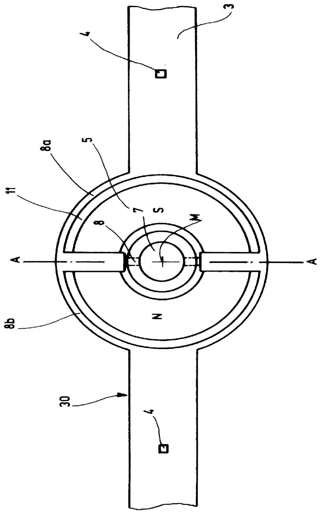
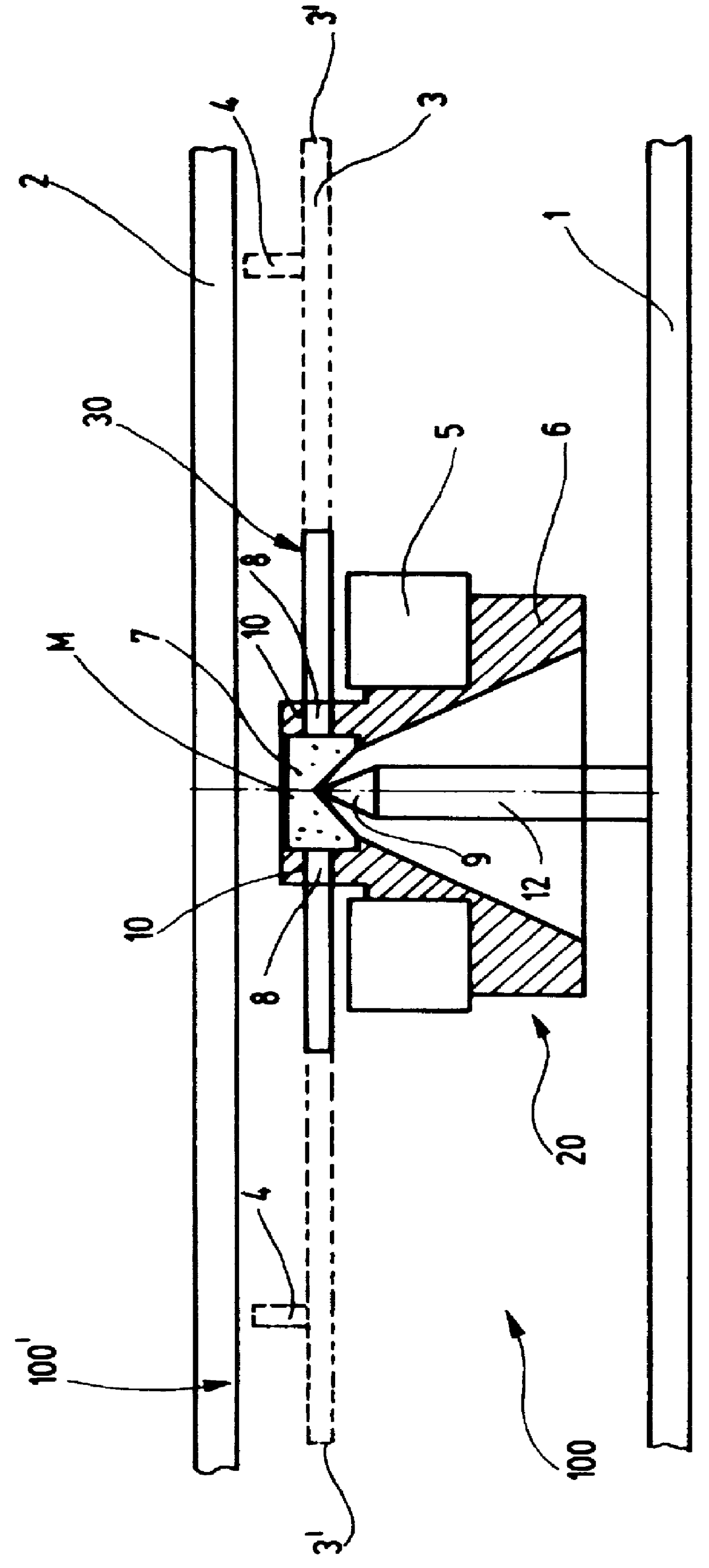
The embodiment of a tilt-compensated indicator device 30 for a compass 100, as depicted in FIGS. 1 and 2, is mounted in a compass housing 100' of which only a transparent top 2 and a preferably likewise transparent bottom 1 are illustrated in FIG. 2. The compass housing 100', which is bounded by the bottom 1 and the top 2, contains preferably a fluid as a gas which serves mainly to damp the movement of the indicator system 30. A magnetic field detection means, indicated generally by the reference number 20, is mounted via a pivot bearing 7 located on the tip 9 of a shaft 12 which is attached to the bottom 1. Such magnetic field detection means is attached to the pivot bearing 7 which is located on the tip 9 of the shaft 12, the bearing being manufactured preferably from a synthetic ruby, a magnet carrier 6 which is firmly connected to the pivot bearing 7, and a permanent magnet 5 having a preferably cylindrical shape. The pivot bearing 7, together wit...


PUM


Abstract

PCT No. PCT / EP96 / 02467 Sec. 371 Date Dec. 5, 1997 Sec. 102(e) Date Dec. 5, 1997 PCT Filed Jun. 5, 1996 PCT Pub. No. WO96 / 41128 PCT Pub. Date Dec. 19, 1996The present invention provides a compass comprising an at-least-partially-transparent housing having a top and a bottom, a vertically orientated, conical pivot bearing, and a magnetic detection means which is mounted on the vertically-oriented conical pivot bearing. The magnetic detection means thereby is capable of rotating in a substantially-horizontal plane. The magnetic field detection means is provided with a radially-extending, tilt-compensating, indicator device. The indicator device has at least one spacer element which is spaced from the magnetic field detection means, the spacer element projecting from the indicator device and being directed towards one of a top of the housing of the compass and a bottom of the housing of the compass. By this structure, the indicator device is guidable in the housing of the compass substantially-parallel to at least one of the top of the housing of the compass and the bottom of the housing of the compass by being mechanically pushed off at least from one of the top of the housing of the compass and the bottom of the housing of the compass by the spacer element when the housing is tilted. In addition, the spacer element which is arranged on the indicator device is oriented in respect to the top of the housing of the compass or the bottom of the housing of the compass in such a manner that an abutting of the indicator device against the housing of the compass can be prevented.

Description

1. Field of the InventionThe invention relates to a tilt-compensating indicator device for a compass having a magnetic field detection means which is mounted on a conical pivot bearing, the magnetic field detection means being capable of rotating in an essentially horizontal plane when the conical pivot bearing is vertically orientated, which is located in a housing of the compass, comprising a bottom and a top.2. Description of the Prior ArtA tilt-compensating indicator device of this type is known from Swiss Patent No. 683,373 which is owned by the applicant. This commercially marketed tilt-compensating indicator device, which has proved its usefulness in practice, is separately mounted from the magnetic field detector and is connected with it by means of a dog. This avoids the disadvantages which occurr in a customary mechanical compass in which the indicator device is rigidly and directly connected to, or is identical with the magnetic field detector, namely that when the compas...

Claims


Application Information

Patent Timeline
Patent Type & Authority Patents(United States)
IPC IPC(8): G01C17/00G01C17/06
CPCG01C17/06
Inventor GLOOR, HANSGIGON, DENIS
Owner RECTA
Why Eureka
Try Eureka