
Personal propulsion device with hands free control

a propulsion device and hands-free technology, applied in the direction of cycle equipment, vessel parts, vessel construction, etc., can solve the problems of inconvenient or inconvenient long-distance travel, difficulty in straight line travel and maneuverability, and inability to adjust the center of resistance of the user's skates, so as to improve aerodynamics and comfort, the effect of reducing the effort of the locomotiv

Inactive Publication Date: 2008-11-27
BURS JR DONALD WESLEY
View PDF8 Cites 12 Cited by
  • Summary
  • Abstract
  • Description
  • Claims
  • Application Information

AI Technical Summary

Benefits of technology

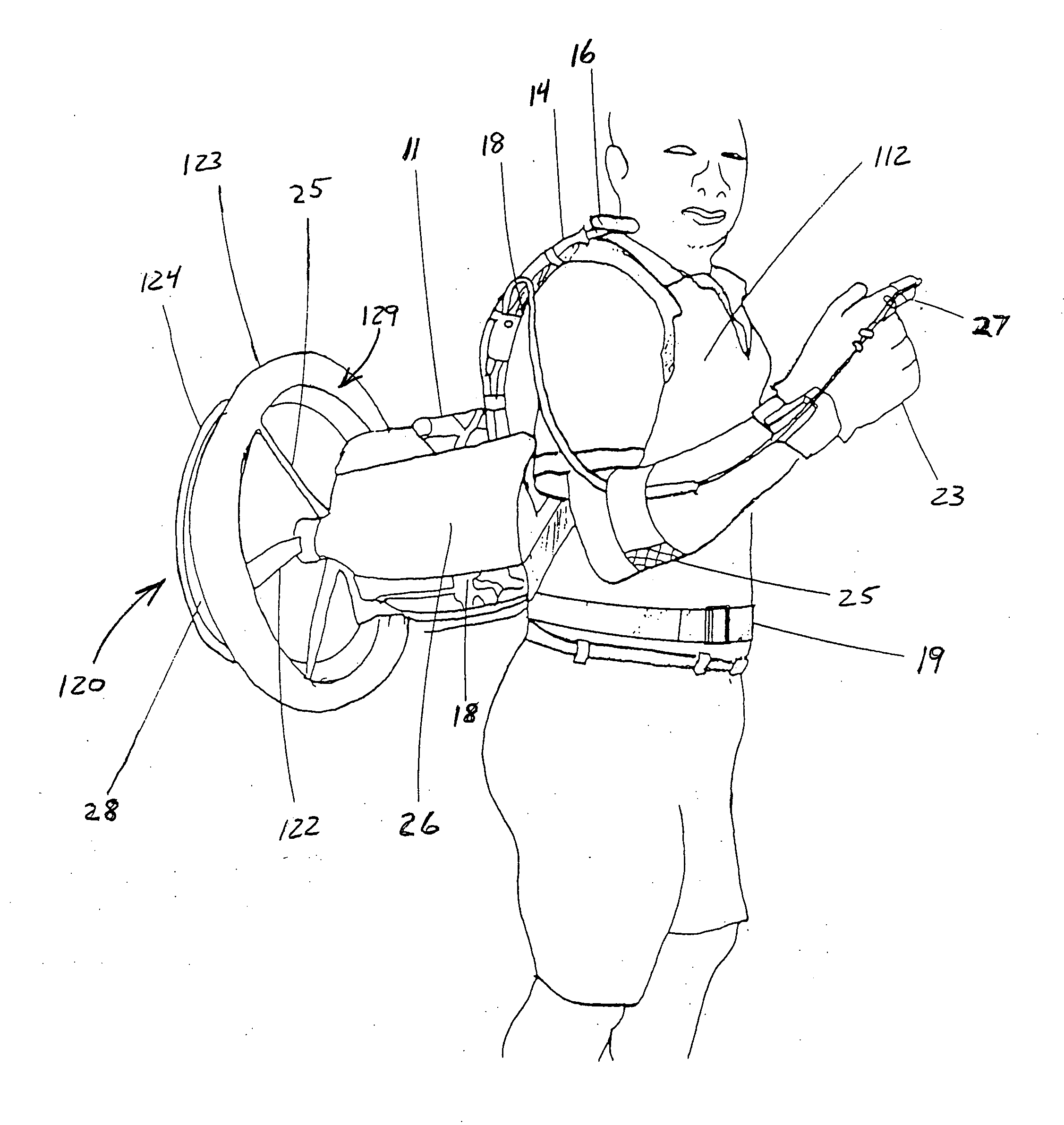
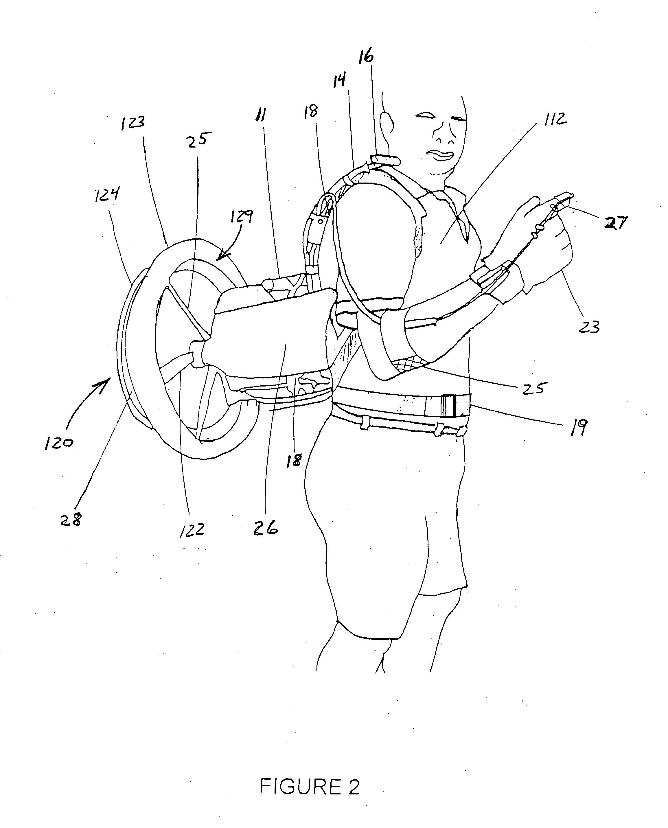
[0032]The current invention generally is worn on the users back to impart thrust to the user to assist traveling on any bicycle, skates, skies, canoe, kayak, wheelchair or other HPVs. The device is adjustable slidable higher and lower on the users back to accommodate the aforementioned vehicles / apparatuses. The personal propulsion device allows hand free control of thrust magnitude so the user can grasp and operate any maneuverability or safety controls of above mentioned apparatuses, continuously, while simultaneously controlling said propulsion device. Adjustments of the thrust direction of the propulsion device allow the user to stand oblique to the direction of travel as on a snowboard or skateboard and deliver thrust inline with the direction of travel. The user can lean forward on a bicycle on a racing position to improve aerodynamics and comfort and the device can be adjusted to deliver horizontal thrust. Thus the reader can see that the user can travel economically and effortlessly on any HPVs or apparatus' for reducing locomotive effort.

Problems solved by technology

Unfortunately, the user is imbalanced by the offset weight and the center of thrust is in line with the one supporting arm of the user and, therefore, misaligned or offset from the center of resistance of the user's skates, as shown in FIG. 3 of that patent.
Torque about the user's vertical axis makes straight line travel and maneuverability difficult.
Support of the device by one arm will rapidly become fatiguing to that arm and long duration travel will be uncomfortable or intolerable.
The support bar along the side of the user, the gas tank and the throttle appendage in front of the user become a hazard in the event of a fall.
The engine is located behind the propeller, thereby increasing the distance from the support and, therefore, increasing the cantilevered weight to the user's arm.
Riding a modern bicycle with only one hand is dangerous as two brake handles are provided for safety in traffic.
The engine would interfere with sitting in the wheelchair.
In a canoe or kayak, the engine would interfere with both hands and arms being required for the paddles.
An engine speed of 18,000 to 20,000 rpm is dangerous as propellers can and do shatter, which may cause serious injuries to the user and bystanders.
Six pounds of thrust is low and insufficient for overcoming inclines and soft snow with heavier users, and slow in watercraft against even a light wind.
The frame top terminates in rigid tube ends which during a fall may on contact with the back or sides of the head and neck cause injury to the user.
The control bars at the sides of the user present a further injury hazard in the event of a fall.
The unit would be impossible to operate on a bicycle, and the position on the user's body would interfere with a canoe, kayak and wheelchair.
On snow skis the requirement of both hands and both arms renders the user unable to grip and maneuver the pair of ski poles essential for balance, turning and accelerating over rough terrain.
The many parts, heavy weight, high cost of manufacturing, hazardous in a fall, and both hands and arms occupied, make this invention less attractive as an alternative form of transportation.
These side handles are an injury hazard in a fall.
The device is hanging free on the pendulum harness except for the users hands on the two handle grips, so in the event of a fall when the users hands release the handles to break the fall, the unit can swing around the neck or impact the users head and neck causing injury.
The foot starting cable may become entangled around the user causing further injury.
Further more the users hands would be unavailable to grasp the required maneuvering implements such as paddles, brakes, handle bars, wheels of the wheelchair etc.
If the user released the handles to grasp implements the unit would swing out of control causing an impact hazard.
This close tolerance requires stiffened duct and vane arrangement and the cost of the composites and manufacturing of them, to stiffen the unit and retain the light weight features required in aircraft is prohibitive for a personal propulsion device.
The rpm is also increased in a ducted fan and results in an unacceptable blade failure risk proximate to crowd and children on bicycle paths, sidewalks, and boardwalks for ground transportation.
None of the prior art machines adjust slidably up high on the users back and down low on the users back.
This position removes the strength and leverage advantage of the operators arm, against the load, due to the inconvenient position.
The prior art of personal propulsion means attached directly to the user has resulted in heavy, slow and generally inefficient devices.
There are handles and appendages that create a safety and / or injury hazard to the user in the event of a fall.
The devices lack sufficient adjustments in position on user, and thrust angle to provide wide versatility in cooperation with the many HPVs available today.
As a result, presently there are no personal propulsion devices that are widely available on the market, therefore, the public has benefitted little from the prior art devices.
Emerging countries' fuel demand in conjunction with the aforementioned pressures, point to ever increasing prices and ever tightening supplies.
This is occurring in large cities and small towns alike, as the negative impact of too many automobiles is pervasive.
The range of HPVs has always been limited by the endurance of the user and thereby eliminating much of the public from benefitting from such devices.

Method used


Image

  • Personal propulsion device with hands free control
  • Personal propulsion device with hands free control
  • Personal propulsion device with hands free control

Examples


Embodiment Construction

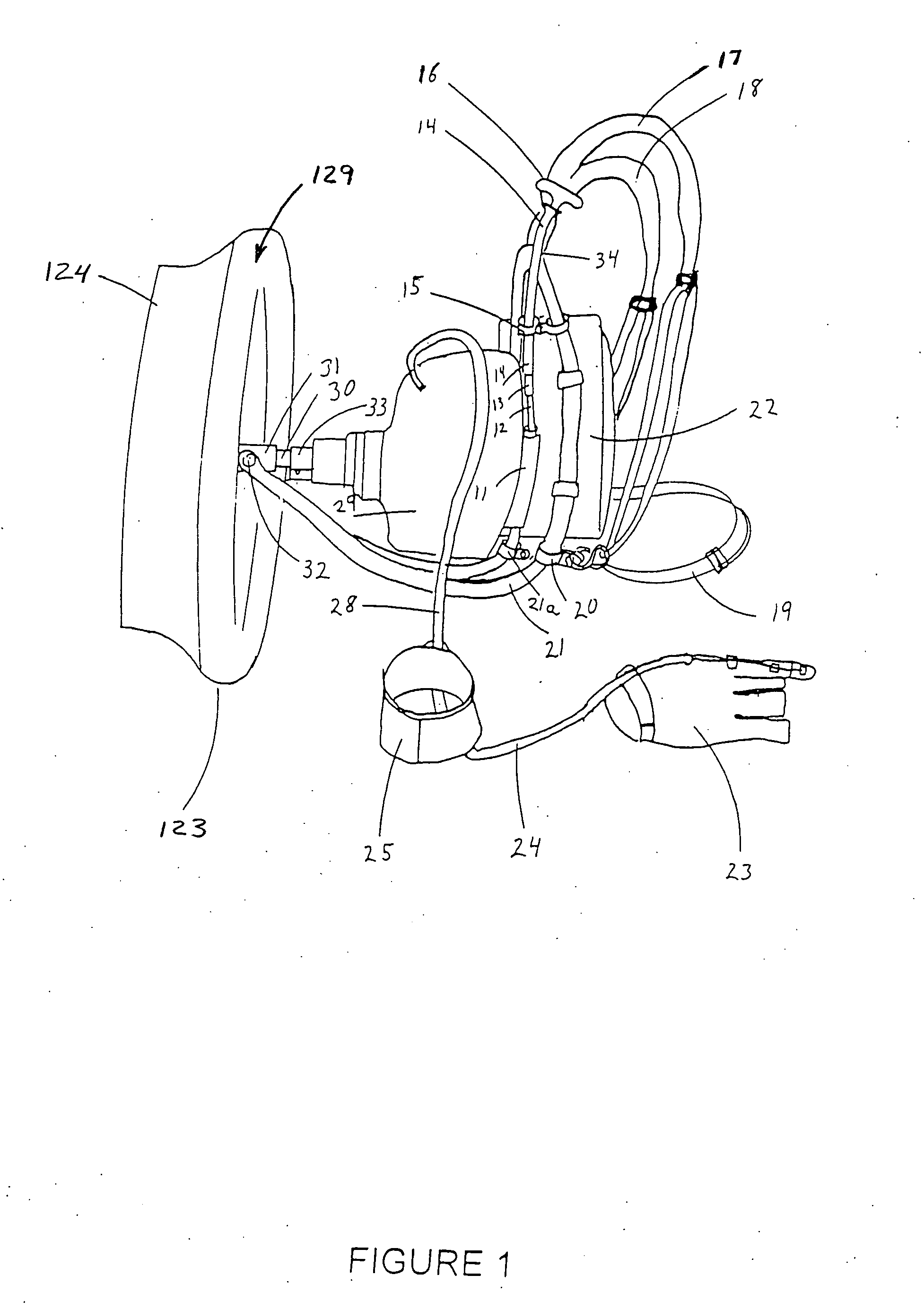
[0053]As shown in FIG. 1, in the preferred embodiment of the personal propulsion device 11 of the present invention the motor 29 contains a vibration isolated motor mount clamp 33 and is secured to the propeller shaft housing tube 30. The pivot block 31 slides onto the propeller drive shaft housing tube 30 and is clamped securely by tightening pivot block bolt 32. The pivot block 31 is attached to a light weight aluminum frame 21 with the pivot block bolt 32. As the pivot block bolt 32 is tightened it secures other parts, shown in detail in FIG. 11, simultaneously. A comfort pad 22 is secured to frame 21 and padded adjustable shoulder straps 17 and 18 are attached to the top of the frame 21 and secured to bottom of frame 21 with clamps 20 and 20a. The adjustable waist belt 19 is also attached to clamps 20 and 20a. The throttle control glove 23, which is shown in detail in FIG. 3, is connected to the motor 29 using a standard throttle cable 24 and ignition switch in general use today...


PUM


Abstract

An improved personal propulsion device that generally imparts thrust directly to the user. The device allows hands free control of thrust magnitude and direction so both hands can grasp and control bicycle handlebars and brakes, watercraft paddles, ski poles or other apparatuses. The device is adjustable vertically, on the users' back, higher to allow sitting in a canoe or wheelchair and lower for standing on skates, skis, kick scooters etc. A user on a bicycle may prefer to lean forward for comfort and aerodynamics, a device adjustment compensates and delivers level thrust. A user on a snowboard or skateboard stands oblique to the direction of travel, a device adjustment allows in line thrust. Both users' hands and arms are free to balance, protect others by pushing off or break a fall. The present invention can be provided as separate modules that allow interchangeability and use with a direct drive mechanism.

Description

CROSS-REFERENCE TO RELATED APPLICATIONS[0001]This application claims the benefit of U.S. patent application Ser. No. 11 / 477,238 filed Jun. 28, 2006, which issued as U.S. Pat. No. 7,331,833 on Feb. 19, 2008.FEDERALLY SPONSORED RESEARCH[0002]Not Applicable.SEQUENCE LISTING OR PROGRAM[0003]Not Applicable.BACKGROUND OF THE INVENTION[0004]A. Field of the Invention[0005]This invention generally relates to personal propulsion devices that are worn on the back of a user or attachable to a moveable object, such as a bicycle, canoe, skateboard or other human-powered vehicle, ridden by the user to propel the user and the object. More specifically, this invention relates to such devices that provide for hands-free operation and control of the device and are configured to accept adjustments for versatility. Even more specifically, this invention relates to various improvements to the configuration of such devices that improve the usefulness and functionality of the device.[0006]B. Prior Art[0007...

Claims


Application Information

Patent Timeline
Patent Type & Authority Applications(United States)
IPC IPC(8): B62B15/00
CPCA63C17/267B62K23/02B62M6/10B62M7/08B62M23/02B63H7/02
Inventor BURGESS, JR., DONALD WESLEY
Owner BURS JR DONALD WESLEY
Learn More