Light source

a technology of light source and light source, which is applied in the direction of electrical equipment, instruments, lighting and heating equipment, etc., can solve the problem of uneven light distribution

Inactive Publication Date: 2000-08-01
UNISPLAY
View PDF10 Cites 127 Cited by
  • Summary
  • Abstract
  • Description
  • Claims
  • Application Information

AI Technical Summary

Problems solved by technology

This disadvantage arises from the construction of the light source of the lamp.
This large percentage is a major cause of the unevenness of light distribution.

Method used


Image

  • Light source
  • Light source
  • Light source

Examples


Embodiment Construction

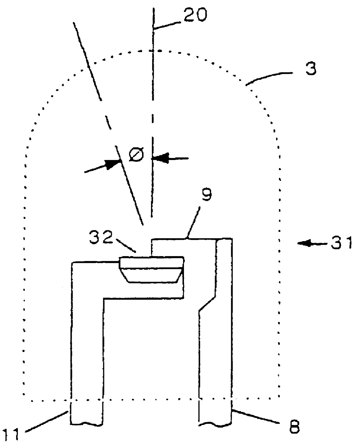
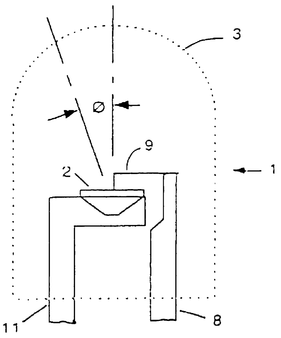
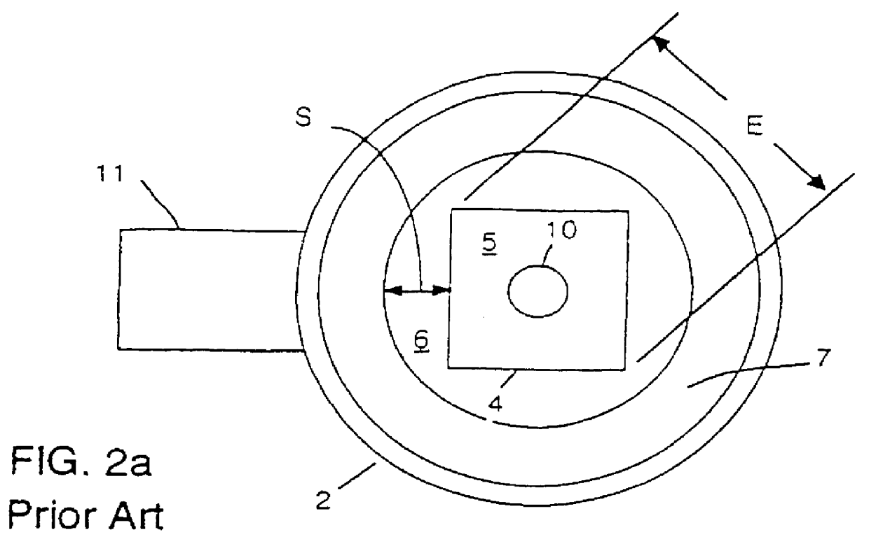
FIGS. 5, 6, 7 illustrate a lamp using a light source 32 according to an embodiment of the invention. Cylindrical lamp 31 with a body of translucent material includes a lens 3 arranged to concentrate light from light source 32 towards the viewer. Light source 32 has a hollow formed in it by coining or other means comprising a lower portion 52 and an upper portion 53. Lower portion 52 has the form of a shallow well with a rectangular floor 36 and four planar walls 51 rising from floor 36 more or less vertically. Upper portion 53 comprises four side reflectors 37-40 and four corner reflectors 41-44. The length of each side reflector is approximately equal to the length of the top edge of the chip side face associated with the reflector. For example, the length of side reflector 38 is approximately equal to W. If spacing "d" around the chip is large, the length of each side reflector may exceed the length of the top edge of the chip side face associated with the reflector. Side reflecto...


PUM


Abstract

An LED light source for a lensed lamp is described. An LED chip sits in a hollow having a rectangular floor. A lower portion of the hollow has steep walls and accommodates the part of the chip that does not emit light. An upper part of the hollow has four side reflectors extending parallel to the sides of the chip and four corner reflectors. The hollow is formed by coining. The light source provides more uniform light than do previous arrangements having convergent lenses. The vertical viewing angle of the lamp is maintained throughout the whole of the horizontal viewing angle range of the lamp.

Description

FIELD AND BACKGROUND OF THE INVENTIONThe present invention relates to LED lamps that use a convergent lens to intensify the light projected by the lamp. FIG. 1 illustrates a widely used arrangement for such lamps. Light from light source 2 is concentrated by lens 3 towards the viewer. FIG. 2a is a plan view of the light source of FIG. 1. Light source comprises an LED chip 4 having a light emitting front face 5. The chip is mounted on a flat internal floor 6 of light source 2. Floor 6 terminates in a conically shaped reflector 7 which reflects light from the sides of chip 4 towards lens 3. During energisation of lamp 1 current flows from terminal lead 8 through thin bonding wire 9 to bonding pad 10 of chip 4 and from the base of chip 4 out through terminal lead 11. Lead 8 and thin bonding wire 9 are not shown in FIG. 2. When current flows light source 2 appears as shown in FIG. 3, in which areas 12, 13, shown dotted, are luminous and areas 14, 15 are dark. If the light pattern of FIG...

Claims


Application Information

Patent Timeline
Patent Type & Authority Patents(United States)
IPC IPC(8): H01L33/00G02B5/08G02B3/00H01L33/60
CPCH01L33/60Y10S362/80H01L2224/48095H01L2224/48247H01L2224/48463
Inventor SALAM, HASSAN PADDY ABDEL
Owner UNISPLAY
Why Eureka
Try Eureka