Speech synthesis system

a synthesis system and speech technology, applied in the field of speech synthesis system, can solve the problems of heavy traffic in the lan, inefficient function of the client 1, and insufficient use of client 1 resources

Inactive Publication Date: 2000-08-01
FUJITSU LTD
View PDF22 Cites 46 Cited by
  • Summary
  • Abstract
  • Description
  • Claims
  • Application Information

AI Technical Summary

Problems solved by technology

The above described conventional speech synthesis system has a problem in that there is heavy traffic in a LAN because the system transmits voice data (synthesized voice waveforms) directly between the client 1 and the voice synthesizing server 2.
Additionally, since the conventional speech synthesis systems execute communication between a server and a client using fixed type data regardless of the server's and the client's resources (functions), they have another problem in that the resources of the client 1 are not made use of much.
Thus, the function of the client 1 is not utilized efficiently.
Therefore, the conventional systems have a further problem that only clients having the D / A converting function can receive voice data.
However, no conventional systems have the function.
However, no conventional systems cover such functions.

Method used


Image

  • Speech synthesis system
  • Speech synthesis system
  • Speech synthesis system

Examples


embodiment 1

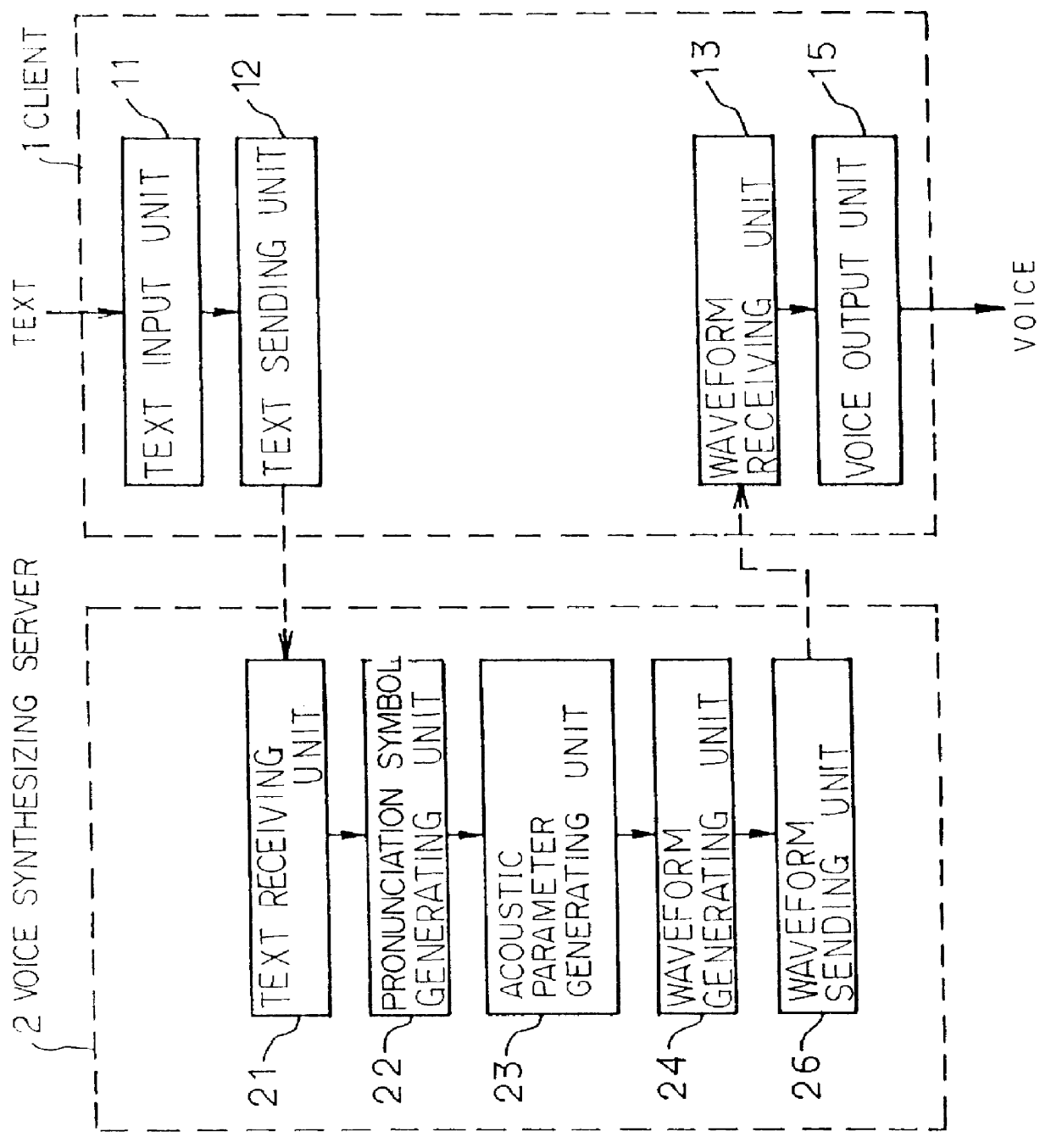
FIG. 8 shows the configuration of the speech synthesis system of embodiment 1 of the present invention. The embodiment shows the case in which at least one voice synthesizing server 20 and a plurality of clients 10 are connected to a LAN.

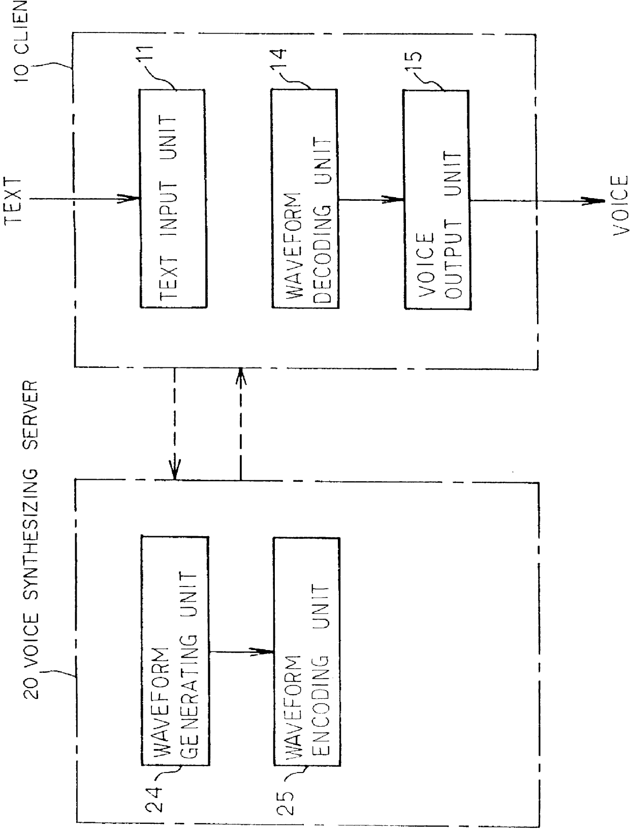
The client 10 includes the text input unit 11 for receiving as text data a message to be processed to synthesize voice, the text sending unit 12 for sending to the voice synthesizing server 20 the text data inputted to the text input unit 11, the waveform receiving unit 13 for receiving an encoded voice waveform sent from the voice synthesizing server 20, the waveform decoding unit 14 for decoding the received voice waveform, a D / A converting unit 151 for converting the decoded voice digital data to analog data, and a low-pass filter 152 for removing high frequency components from the analog data. A speaker 153 is connected to the low-pass filter 152.

The voice synthesizing server 20 includes the text receiving unit 21 for receiving text data receive...

embodiments 2 and 3

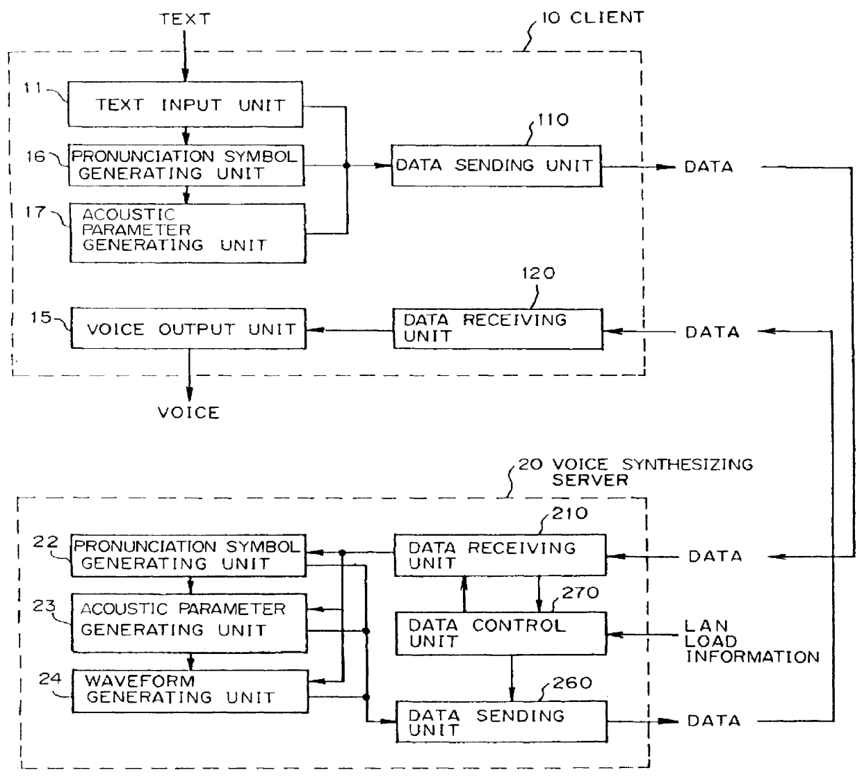
FIG. 18 shows the configuration of the system in embodiment 2 of the present invention in which the client 10 has the function of generating pronunciation symbols. FIG. 19 shows the configuration of the system in embodiment 3 of the present invention in which the client 10 has the function of generating acoustic parameters.

embodiment 2

The client 10 in embodiment 2 shown in FIG. 18 includes the text input unit 11, the pronunciation symbol generating unit 16, the pronunciation symbol sending unit 100 as the data sending unit 110, the waveform receiving unit 13 as the data receiving unit 120, the waveform decoding unit 14, and the voice output unit 15.

The client 10 in embodiment 3 shown in FIG. 19 includes the text input unit 11, the pronunciation symbol generating unit 16, the acoustic parameter generating unit 17, the acoustic parameter sending unit 101 as the data sending unit 110, the waveform receiving unit 13 as the data receiving unit 120, the waveform decoding unit 14, and the voice output unit 15.

In each embodiment, the voice synthesizing server 20 includes the data receiving unit 210, the pronunciation symbol generating unit 22, the acoustic parameter generating unit 23, the waveform generating unit 24, the waveform encoding unit 25, the data sending unit 260, and the data control unit 270.

The data control...


PUM


Abstract

The data control unit in the voice synthesizing server of the present invention receives from a client data to be processed to synthesize voice, and determines the type of the received data. If the received data are text data, they are outputted to the pronunciation symbol generating unit to generate pronunciation symbols. If the received data are pronunciation symbols, they are outputted to the acoustic parameter generating unit to generate acoustic parameters. If the received data are acoustic parameters, they are outputted to the waveform generating unit to generate voice waveforms, and the generated voice waveforms are sent from the data sending unit to the client. The client receives the voice waveforms from the voice generating server, and outputs the received voice waveforms as voice from the voice output unit.

Description

1. Field of the InventionThe present invention relates to a speech synthesis system in which a plurality of clients and at least one voice synthesizing server are connected to a local area network (LAN).2. Description of the Related ArtSystems for synthesizing voice from text data at a client's request and transmitting the result to the client have become popular. These systems include a voice synthesizing server and more than one client on a LAN. FIG. 1 shows a basic configuration of such systems. A client 1 includes a text input unit 11, a text sending unit 12, a waveform receiving unit 13, and a voice output unit 15. A voice synthesizing server 2 includes a text receiving unit 21 for receiving text data sent from the text sending unit 12, a pronunciation symbol generating unit 22, an acoustic parameter generating unit 23, a waveform generating unit 24, and a waveform sending unit 26 for sending to the client 1 a voice waveform synthesized by the waveform generating unit 24.When t...

Claims


Application Information

Patent Timeline
Patent Type & Authority Patents(United States)
IPC IPC(8): G10L13/00G10L13/04H04M11/00H04M3/487H04M7/00G10L13/02G10L13/047
CPCH04M11/00G10L13/047H04M3/487G10L13/02G10L13/00H04M7/006H04M2201/60
Inventor MATSUMOTO, TATSURO
Owner FUJITSU LTD
Why Eureka
Try Eureka