Planar connector

a technology of connectors and planar connectors, applied in the direction of electrical equipment, electrical discharge tubes, coupling device connections, etc., can solve the problems of cable equipped with edge-card connectors being difficult to autoclave, and the life of edge-card connectors is generally shor

Inactive Publication Date: 2000-08-08
THE WHITAKER CORP
View PDF5 Cites 44 Cited by
  • Summary
  • Abstract
  • Description
  • Claims
  • Application Information

AI Technical Summary

Problems solved by technology

While the cables having edge-card connectors may not be discarded along with the handpiece after each use, they, however, suffer from other shortcomings.
For example, the edge-card connectors generally have a short life span, thus requiring users to frequently replace the cables, including the accompanying connectors.
Additionally, cables equipped with edge-card connectors are more difficult to autoclave, making sterilization a time consuming and / or expensive process.
Replacing the cables and connectors every time a medical handpiece is discarded is not only inconvenient, but it is also expensive.

Method used


Image

  • Planar connector
  • Planar connector
  • Planar connector

Examples


Embodiment Construction

Illustrative embodiments of the invention are described below. In the interest of clarity, not all features of an actual implementation are described in this specification. It will of course be appreciated that in the development of any such actual embodiment, numerous implementation-specific decisions must be made to achieve the developers' specific goals, such as compliance with system-related and business-related constraints, which will vary from one implementation to another. Moreover, it will be appreciated that such a development effort might be complex and time-consuming, but would nevertheless be a routine undertaking for those of ordinary skill in the art having the benefit of this disclosure.

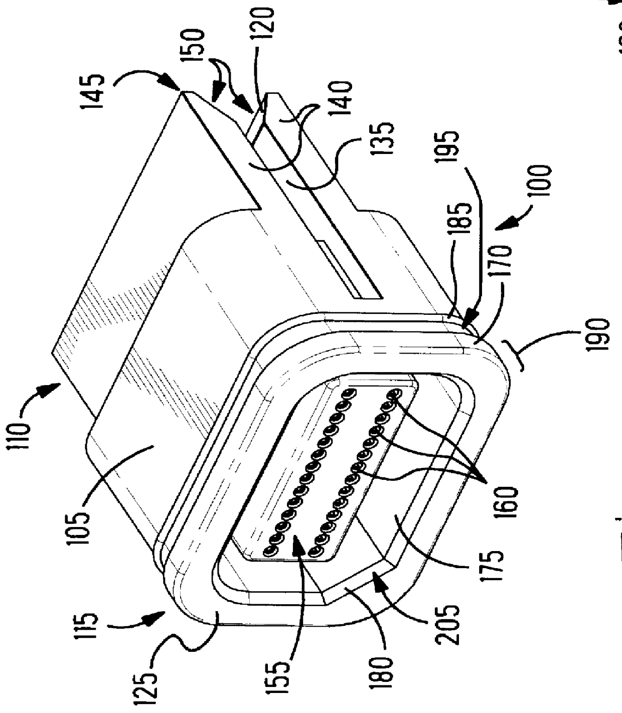
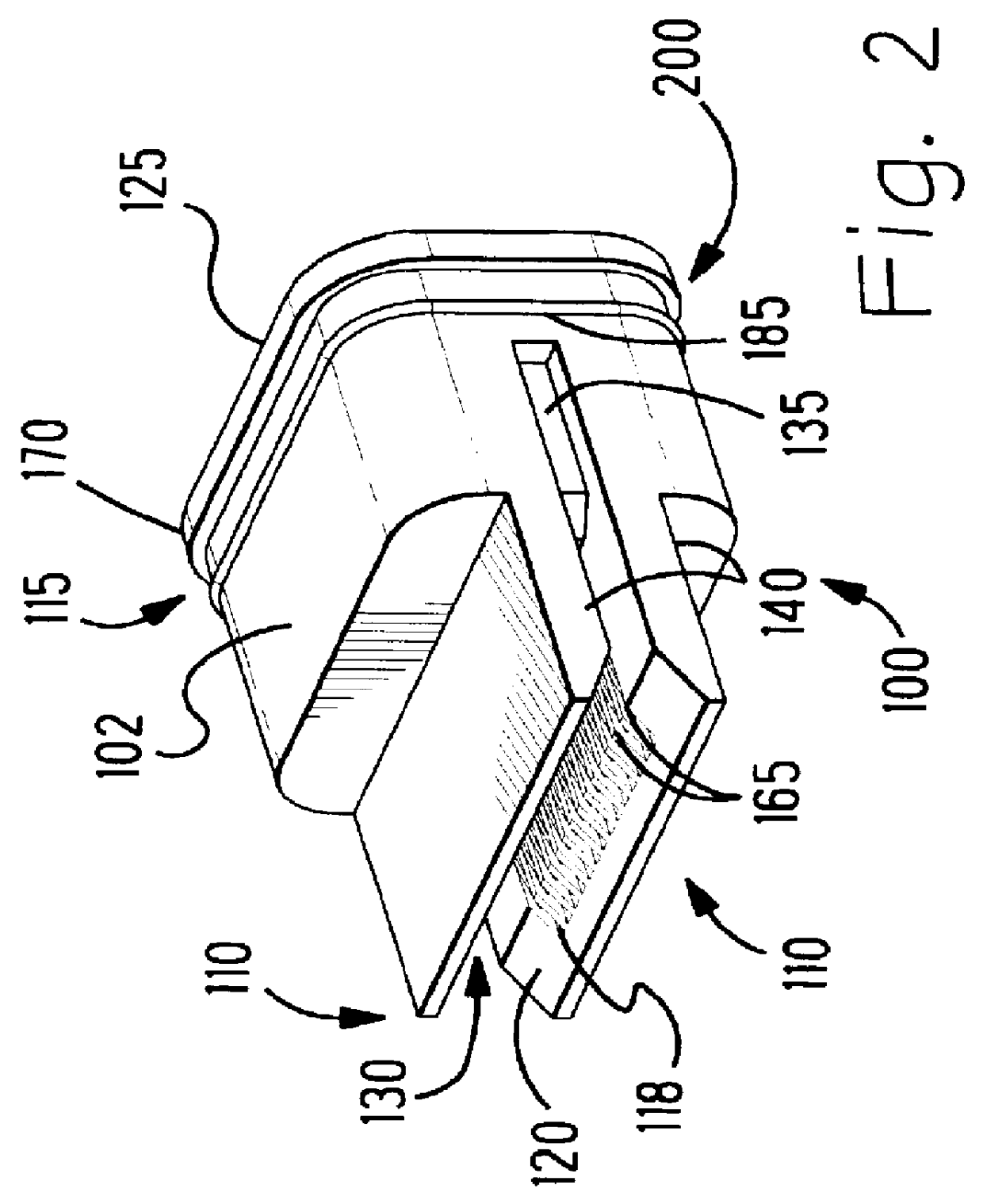
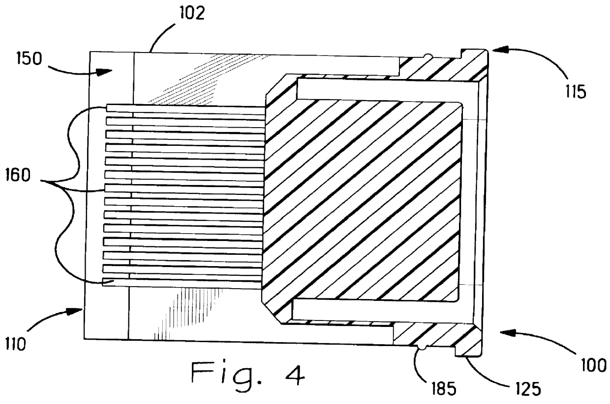
Referring now to the drawings, and in particular to FIGS. 1-6, a planar connector 100 is illustrated in accordance with the present invention. The planar connector 100 comprises a housing 105 having a first and a second end portion 110, 115, wherein a first interface 120 is located adj...


PUM


Abstract

The present invention is directed to a connector and a system. The connector 100 includes a housing 105 having a first and a second end portion 110, 115, and a contact having a first and a second end portion. The connector further comprises a printed circuit board interface 120 and a second interface 125. The printed circuit board interface 120 is located adjacent the first end portion 110 of the housing 105, the printed circuit board interface 120 adapted to receive the first end portion of the contact. The second interface 125 is located adjacent the second end portion 115 of the housing 105 and adapted to mate with a plug connector 610, the second interface 125 having a second contact adapted to receive the second end portion 115 of the contact. The system 710, 910 comprises a mating plug connector 610 capable of mating with the connector 100.

Description

1. Field of the InventionThis invention relates generally to electrical connectors, and, more particularly, to a planar connector for a printed circuit board (PCB).2. Description of the Related ArtIt is not uncommon to find electrical devices ranging from catheters to computers that have a printed circuit board (PCB) that can be plugged into a variety of connectors. Generally, a connector that attaches to a PCB of a device such as a catheter, microphone, or the like (hereinafter referred to as a "handpiece") is hardwired to a cable, which connects the handpiece to another electrical device, such as a controller, for example. Alternatively, cables that are not directly hardwired to the handpieces come equipped with an edge-card connector affixed to one end of the cable, which then attaches to the PCB of the handpiece.Typically, to prevent contamination, handpieces utilized in the medical field are discarded after every use. Accordingly, a cable that is hardwired to a disposable medic...

Claims


Application Information

Patent Timeline
Patent Type & Authority Patents(United States)
IPC IPC(8): H01R31/06H01R12/72
CPCH01R12/721H01R31/06Y10S439/909H01R2201/12
Inventor TROYAN, BRUCE ROBERT
Owner THE WHITAKER CORP
Why Eureka
Try Eureka