Pushbutton switch and input device using the same
- Summary
- Abstract
- Description
- Claims
- Application Information
AI Technical Summary
Benefits of technology
Problems solved by technology
Method used
Image

Examples
exemplary embodiment 1
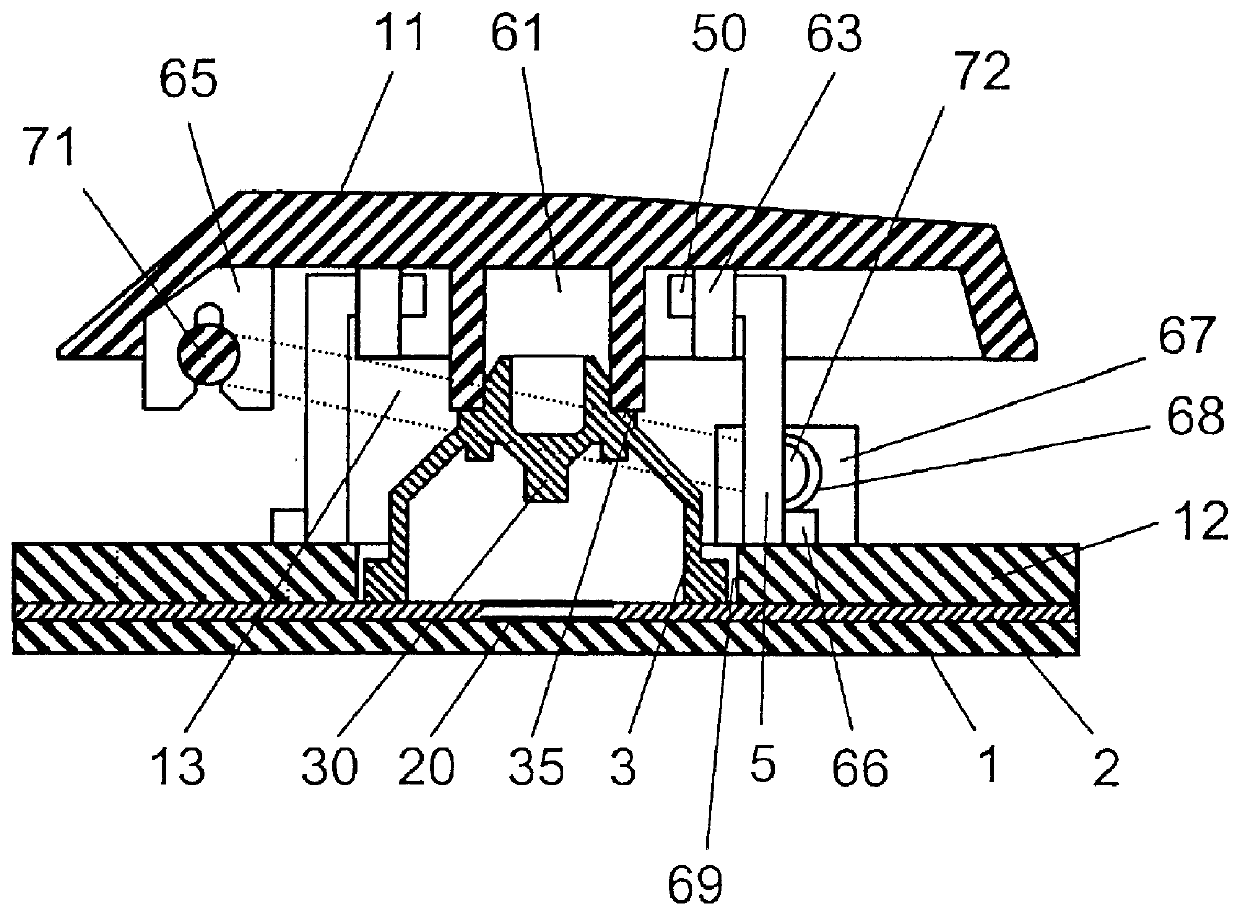
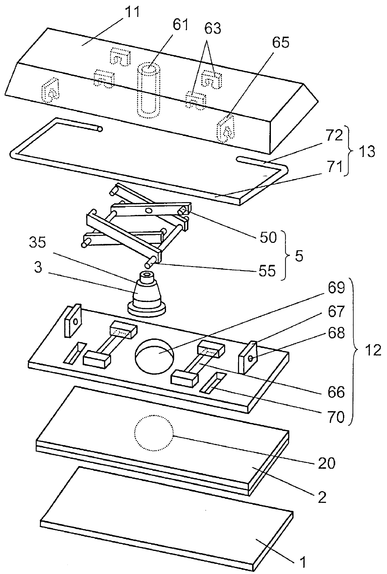
FIG. 1 is a lateral cross section of a pushbutton switch in accordance with the first exemplary embodiment of the present invention, and FIG. 2 shows a perspective exploded view of the pushbutton switch shown in FIG. 1.
In both FIG. 1 and FIG. 2, a base member includes switch member 2 disposed on a metallic substrate 1, and a resin-molded fixture 12 mounted to an upper face of switch member 2. Switch member 2 comprises two films bonded to each other and a switch contact 20 in between. An elastic body is, for example, a rubber dome 3, and has a depending protrusion 30 at upper inside portion thereof. Protrusion 30 is used for depressing switch contact 20. Rubber dome 3 is placed on switch member 2 through a round hole 69 formed in fixture 12 so that protrusion 30 can be located above switch contact 20.
An elongated key-top 11, e.g. a space bar, is provided with a cylindrical stem 61 at the center of its lower face. Stem 61 presses against an outer wall 35, which is donut-shaped when vi...
exemplary embodiment 2
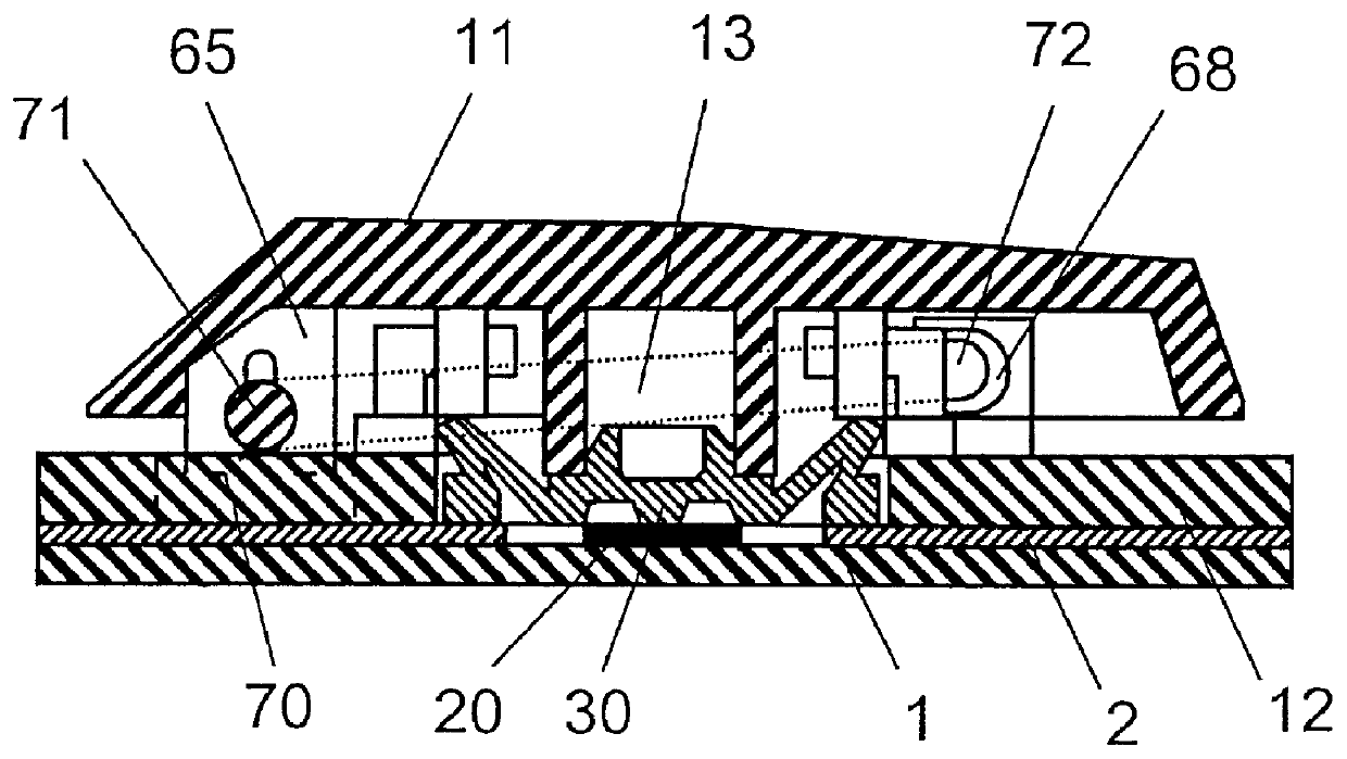
FIG. 5 is a front cross section showing a right end of a pushbutton switch in accordance with the second exemplary embodiment of the present invention, and FIG. 6 is a lateral cross section taken on line 6--6 of FIG. 5. The switch section including the rubber dome is omitted in FIG. 6. FIG. 7 is a perspective exploded view of an essential part of the same pushbutton switch shown in FIG. 5.
The pushbutton switch in accordance with the second exemplary embodiment differs only in an engagement structure between a fixture 14 and a stabilizing member 15 from that of the first exemplary embodiment, and the other features remain the same.
First side 81 of stabilizing member 15 is engaged rotatably with two stoppers 65 provided on a lower face of key-top 11 at the sections near both ends of side 81. Both terminals 82 of the second side, i.e. the open side of stabilizing member 15, are crank-shaped and form approximate right angles with regard to a quadrangle face as shown in FIG. 7. Both term...
exemplary embodiment 3
FIG. 9 is a front cross section showing a right end of a pushbutton switch in accordance with the third exemplary embodiment of the present invention. This pushbutton switch can advantageously eliminate the fixture from that of the second exemplary embodiment.
In FIG. 9, metallic substrate 17 is punched and bent to unitarily form protrusions 92, guide sections 93 and stoppers (not shown) for engaging a lower end of a link member. These elements protrude upwardly through holes (not shown) punched in switch member 18 disposed on an upper face of substrate 17. On the upper end of protrusion 92, a U-shaped groove 91 is formed. Groove 91 holds a second side, i.e. the crank-shaped terminal 85, and guide section 93 engages section 87 of stabilizing member 16.
According to the third exemplary embodiment, fixture 14, shown in FIG. 8 and used in the second exemplary embodiment, can be saved, so that the material cost and assembly cost can be reduced, and further, the space below key-top 11 can ...
PUM
 Abstract
Description
Claims
Application Information