Supporting modification of properties via a computer system's user interface

a technology of user interface and computer system, applied in computing, instruments, electric digital data processing, etc., can solve the problems of requiring significant developer effort, unable to help developers, and unable to achieve user interface and functional consistency, so as to simplify application program development, save development time, and reduce costs

Inactive Publication Date: 2000-08-08
IBM CORP
View PDF20 Cites 84 Cited by
  • Summary
  • Abstract
  • Description
  • Claims
  • Application Information

AI Technical Summary

Benefits of technology

The computer program product according to this aspect preferably provides support for both developing applications which support user modification of properties and for run-time modification of properties in response to user interaction. The program product's set of object classes include a set of particular abstractions including property object definitions that can be used to simplify application program development, saving development time (and so reducing costs) and yet enabling increased interface functionality.
In a preferred embodiment of the invention, the framework includes a predefined set of view attributes for a standard set o...

Problems solved by technology

Currently, when developing application programs, a significant amount of developer effort is required to provide the functionality enabling user selection and invocation of actions or user selection and modification of properties within an application program.
Additionally, there is a significant problem in achieving user interface and functional consistency between and within applications that display different views of properties (or actions) which views are perceived by the user as being the same.
A major reason why providing this support is so time consuming for the developer is that there are often required to be a number of different places within an application where the user can select the same action or property, and a number of views of a particular action or property available for selection by the ...

Method used


Image

  • Supporting modification of properties via a computer system's user interface
  • Supporting modification of properties via a computer system's user interface
  • Supporting modification of properties via a computer system's user interface

Examples


Embodiment Construction

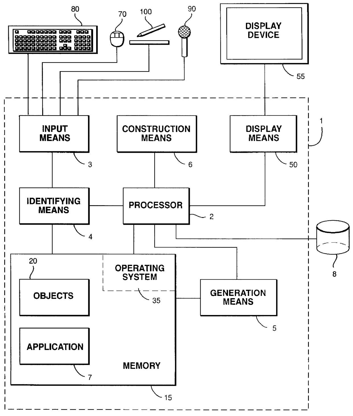
A system according to a preferred embodiment of the invention will be discussed with reference to FIG. 1, which is a block diagram showing the main functional elements of a system in which the invention is implemented. FIG. 1 illustrates a typical computer system 1 having an operating system 35 installed on the computer system, a central processing unit 2, memory 15, a storage device 8 which may be incorporated as part of the system or accessed remotely, and a display device 55 connectable to the computer system.

The processor 2 is arranged to pass data to the display means 50 for display on the display device 55. Since the operation of a typical display means is well known in the art, it will not be discussed in any further detail herein. It suffices to say that it encompasses the various software and hardware components used to pass data to the display device 55. In the IBM OS / 2 operating system, a layer of OS / 2 called Presentation Manager is the software used for this purpose.

In t...


PUM


Abstract

A set of object classes provide a framework supporting user modification of user interface properties. The classes include a properties class which is a template for creation of property objects encapsulating property values and the view attributes (GUI information) required for creating views of the property via a user interface. Property objects provide a single mechanism for representing a particular property, allowing a number of different views to be open on the same property. User interactions with different views of a property via the user interface result in messages being sent to the same property object. If a property value is changed, then the chance is propagated back to all associated applications having views for the object and so view concurrency is automatically achieved.

Description

The present invention relates to computer systems having user interfaces through which a user can select and modify properties associated with components or applications, and to the development of components or applications which support user-modification of properties.The term `component` is used herein to refer to a functional software element of an application program. Components are generally small, self-contained and functional software elements which can be used within a number of different application programs to perform the same function. Components typically implement user-oriented tasks, such as printing for example. A printing component may form a standard building block for applications, and be called each time one of these application programs is run and requires the print operation to be performed. As another example, a calendar facility may be implemented as a component. Building applications from such `shareable` software components is becoming increasingly common, p...

Claims


Application Information

Patent Timeline
IPC IPC(8): G06F3/033G06F9/44G06F3/048
CPCG06F3/0483G06F8/38
Inventor DONNELLY, VANESSATRAINER, RAYMONDJOLIN, ARTHUR THOMAS
Owner IBM CORP
Why Eureka
Try Eureka