Lifting heald

a healing and lifting technology, applied in the field of lifting heald, can solve the problems of still being too short in service life and the inability to guide half heald, and achieve the effect of increasing the service li

Inactive Publication Date: 2000-08-15
GEBR KLOCKER
View PDF8 Cites 16 Cited by
  • Summary
  • Abstract
  • Description
  • Claims
  • Application Information

AI Technical Summary

Benefits of technology

is therefore to provide a lifting heald of the type mentioned above that increases the service life even with very fast running mechanical looms.

Problems solved by technology

Nevertheless, even with this stopper, the service life still was too short, particularly when taking into consideration the increasing number of strokes in the mechanical looms.
But the magnetic force of the second upper magnet has always to be calculated so that the half heald's legs are still reaching the area of the lower magnet, since otherwise the half heald could no longer be guided.

Method used


Image

  • Lifting heald
  • Lifting heald
  • Lifting heald

Examples


Embodiment Construction

)

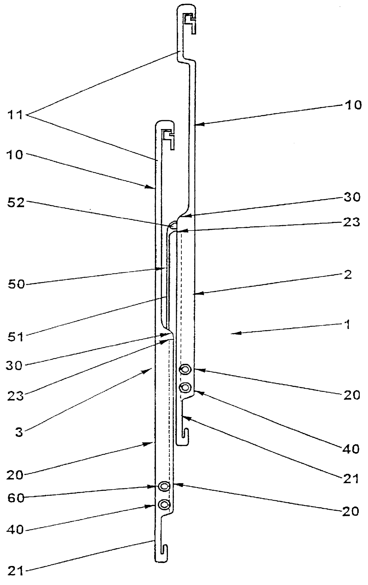
The device 1 for forming a leno selvedge has two lifting healds 2, 3 that may be connected to heald frames moved alternately and that are alternately taking along the half heald 50. The principle of this function is for example described in DE-PS 38 18 680. Reference to this document is explicitely made.

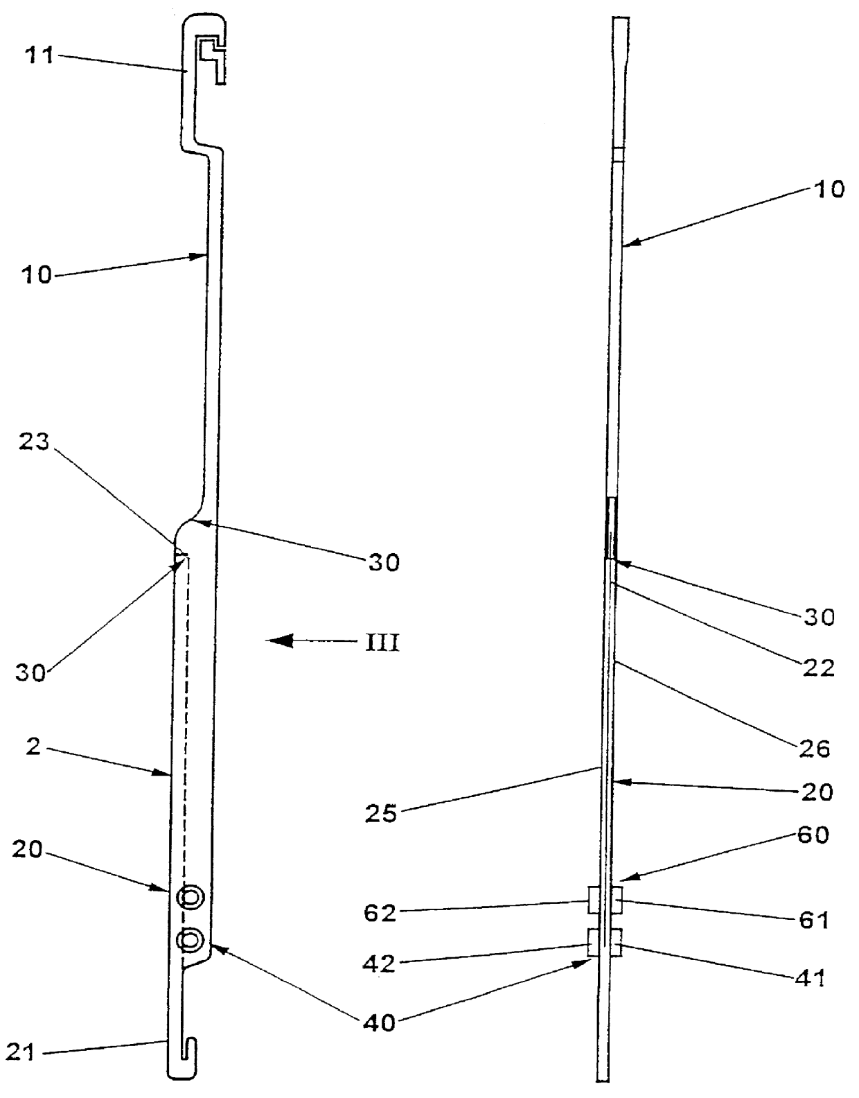
Each lifting heald 2, 3 essentially consists of two legs 10 and 20, each of the legs 10 and 20 being provided with a hook-like element 11 and 21 permitting their fastening on the rods (not shown) supporting the alternately moving healds of the mechanical loom.

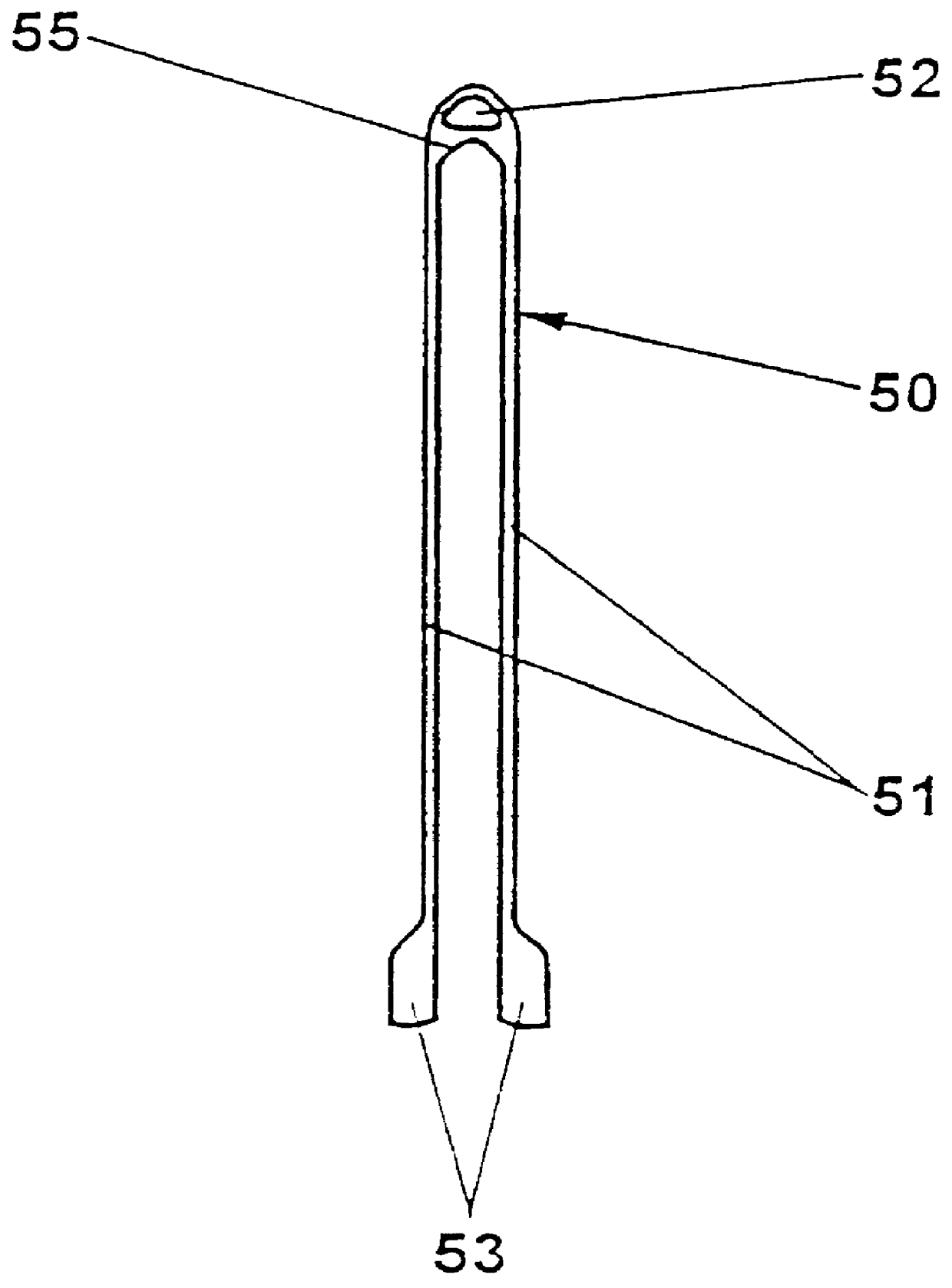
The half heald 50 shown in FIG. 4 has two legs 51 that are converging at their end to an eye 52, whereas a roof-like junction web 55 may be seen underneath the eye. The legs 51 of half heald 50 are provided on their free end with plate-like projections 53.

The leg 20 of the lifting heald 2, 3 shows a slot 22 for the repeated reception of the leg 51 of half heald 50 (FIG. 3). A guide hole 30 is provided at the upper end of leg 20...


PUM


Abstract

A lifting heald assembly is used in a device which forms a leno selvedge on a fabric or hosiery. The heald assembly comprises two lifting healds and one half heald alternately taken along by the lifting healds. Each lifting heald has, in the area of one end, at least one first magnet for guiding the half heald and has a web for taking along the half heald. The spacing between the web and the magnet corresponds approximately to the length of the half heald's legs and the lifting heald (2, 3) is provided with at least one second magnet (61, 62) that is arranged in or on the lifting heald (2, 3) and longitudinally spaced from the first magnet (41, 42) in the direction of the web (23).

Description

1. Field of the InventionThe present invention relates to a lifting heald for a device intended to form a leno selvedge on a fabric or hosiery with two lifting healds and one half heald alternately taken along by the lifting healds, whereas the lifting heald has, in the area of the one end, at least one magnet for guiding the half heald and a web for taking along the half heald, whereas the spacing between the web and the magnet approximately corresponds to the length of the half heald's legs.2. Description of the Prior ArtA lifting heald as mentioned above is known out of DE-PS 38 18 680. The device for forming a leno selvedge hereby consists of two lifting healds arranged on two alternately moved heald frames of a mechanical loom. The device for forming a leno selvedge also has a half heald that is alternately taken along by the movement of the lifting healds. The half heald has two legs converging at their upper end into an eye intended to guide a stationary thread. Such a half h...

Claims


Application Information

Patent Timeline
Patent Type & Authority Patents(United States)
IPC IPC(8): D03C7/00D03C7/02
CPCD03C7/02
Inventor HOCKEMEYER, KURTSCHWEMMLEIN, CHRISTOPH
Owner GEBR KLOCKER
Why Eureka
Try Eureka