Balanced valve operated by the axial driving of a stem displacing a special elastomeric sealing body

a technology of axial driving and valve body, which is applied in the direction of valve details, diaphragm valves, valve member-seat contacts, etc., can solve the problems of high cost and complex nature of the current state of the art valv

Inactive Publication Date: 2000-08-15
PEREZ C SERGIO
View PDF10 Cites 16 Cited by
  • Summary
  • Abstract
  • Description
  • Claims
  • Application Information

AI Technical Summary

Problems solved by technology

Additionally, the valves of the state of the art are complex an

Method used


Image

  • Balanced valve operated by the axial driving of a stem displacing a special elastomeric sealing body
  • Balanced valve operated by the axial driving of a stem displacing a special elastomeric sealing body
  • Balanced valve operated by the axial driving of a stem displacing a special elastomeric sealing body

Examples


Embodiment Construction

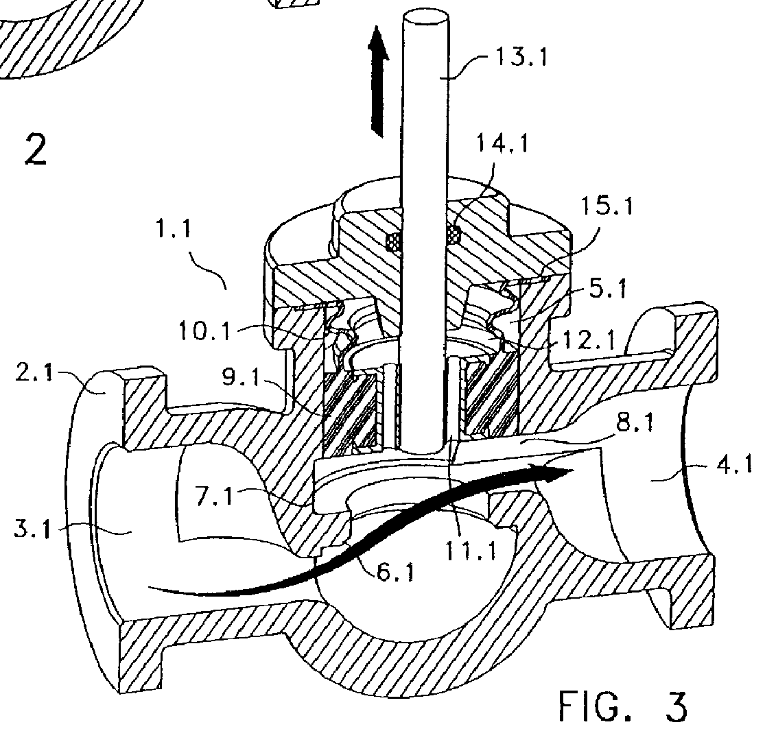
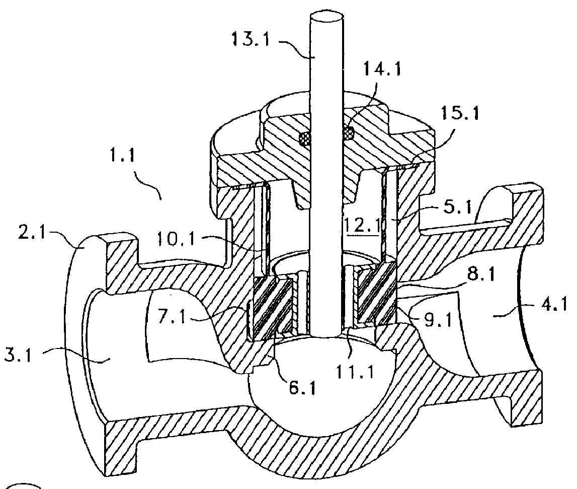
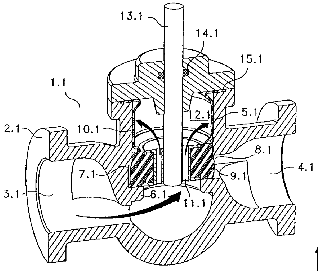
FIGS. 1 through 3 show a first embodiment of the valve of the invention. The valve 1.1 is made up of a valve body 2.1 with an opening for the inlet of flow 3.1 and an opening for the outlet of flow 4.1, which are substantially collineate each other, although they can be angular to each other.

The valve body 2.1 has a cylindrical cavity 5.1 located between the inlet of flow 3.1 and the outlet of flow 4.1, communicating in its opened base with said flow inlet 3.1, and radially communicating with said flow outlet 4.1. The opposing end of the cylindrical cavity 5.1 is substantially closed and, in its opened base, a valve seat 6.1 is defined. The bottom part of the cylindrical cavity 5.1 has a ring-shaped broadening 7.1 acting as port and communicating with the flow outlet 4.1.

In the cylindrical cavity 5.1 an elastomeric sealing body 8.1 is accommodated, which, in this version, is made up of a sealing end 9.1, an axial sealing end in this case, topped out by a cylindrical wall 10.1 with a...


PUM


Abstract

A balanced valve for flows operated by the axial driving of a stem which commands a sealing body liable to axially slip between an opened position far from the valve seat and a closed seal in contact with the valve s eat. The valve basically consists in a valve body having an inlet opening for the flow with a valve seat at the bottom. The valve body also has an opening for the flow outlet oriented in a substantially cross-section way to the flow inlet. Between the inlet and outlet of flow there is a cylindrical cavity with a ring-shaped broadening in the zone communicating with the flow outlet above the valve seat. There is an elastomeric sealing body located inside the cylindrical cavity, which is mainly made up of a relatively solid sealing end, with a slightly greater height than the height of the ring-shaped broadening of the cylindrical activity. This sealing end is provided with one or more axial passes or holes, an d its also has a coaxial zone of radial seal located in the section of upper base of said sealing end, which consists of a circular groove in "V" section at the lower face of the sealing end near its periphery defining a perimetric lug. A variant of the valve considers a cylindrical elastomeric wall topping out the sealing end, which consists of an upper extension of the same sealing end, and topping in its other end in a radial edge withheld in the valve body. This elastomeric cylindrical wall may have one or more reinforcing rings conformed in its mantle and axially arranged.

Description

1. Field of the InventionThe present invention relates to a balanced valve operated by the axial driving of a stem displacing a special elastomeric sealing body, which allows the transfer of flow to a pressure compensating chamber.2. Description of the Related ArtMost of the balanced valves of the state of the art allowing the passing of flow to a pressure compensating chamber, are of a complex structure, said valves offering a substantial rubbing between the sealing body and the walls of the valve along which this body slips. On the other hand, the sealing body of most of these valves requires the participation of additional sealing means to avoid flow leaks from the compensating chamber to the other parts of the valve. Additionally, the valves of the state of the art are complex and costly as regards the change of some components when damaged.This invention, on the contrary, overcomes the disadvantages mentioned for the balanced valves of the prior art.Basically, the valves of the...

Claims


Application Information

Patent Timeline
IPC IPC(8): F16K41/00F16K39/00F16K39/02F16K7/00F16K41/10F16K7/20
CPCF16K7/20F16K39/022F16K41/103
Inventor PEREZ C., SERGIO
Owner PEREZ C SERGIO
Why Eureka
Try Eureka