Methodology for fabricating sliders for use in glide head devices

a technology of glide head and slider, which is applied in the direction of manufacturing tools, mechanical roughness/irregularity measurements, instruments, etc., can solve the problems of difficult to precisely control the electrical response characteristics of the electrical head, the surface burnishing of the manufacture's disk, and the error in the transfer of information or even damage to the data head. , to achieve the effect of reducing structural degradation

Inactive Publication Date: 2000-09-05
MICROGLIDE
View PDF16 Cites 15 Cited by
  • Summary
  • Abstract
  • Description
  • Claims
  • Application Information

AI Technical Summary

Benefits of technology

Yet another object of the present invention is to provide a new and useful methodology for fabricating an improved slider for use in a glide head assembly which slider exhibits reduced structural degradation during the asperity detection process.

Problems solved by technology

The persisting problem with rigid magnetic memory disks is that asperities, i.e. protrusions on surfaces of the disks, may cause an anomaly when encountered by the data head.
These asperities can cause errors in the transfer of information or even damage to the data head during operation.
In an effort to alleviate such occurrences, manufactures commonly burnish the surfaces of disks.
This disturbance causes an electronic signal to be sent to a signal processing circuitry.
However, the same disturbance also causes a variety of other electronic signals to be sent to the signal processing circuitry.
These signals are caused, at least in part, by resonant vibrations of other components in the glide head assembly, as well as inherent noise in the test system.
While it is difficult to precisely control these electrical response characteristics, there is also a drawback to the existing construction for sliders used in conventional glide head devices.
The trailing edge of the slider, therefore, has a tendency to degrade rather rapidly due to its repeated contact with asperities.

Method used


Image

  • Methodology for fabricating sliders for use in glide head devices
  • Methodology for fabricating sliders for use in glide head devices
  • Methodology for fabricating sliders for use in glide head devices

Examples


Embodiment Construction

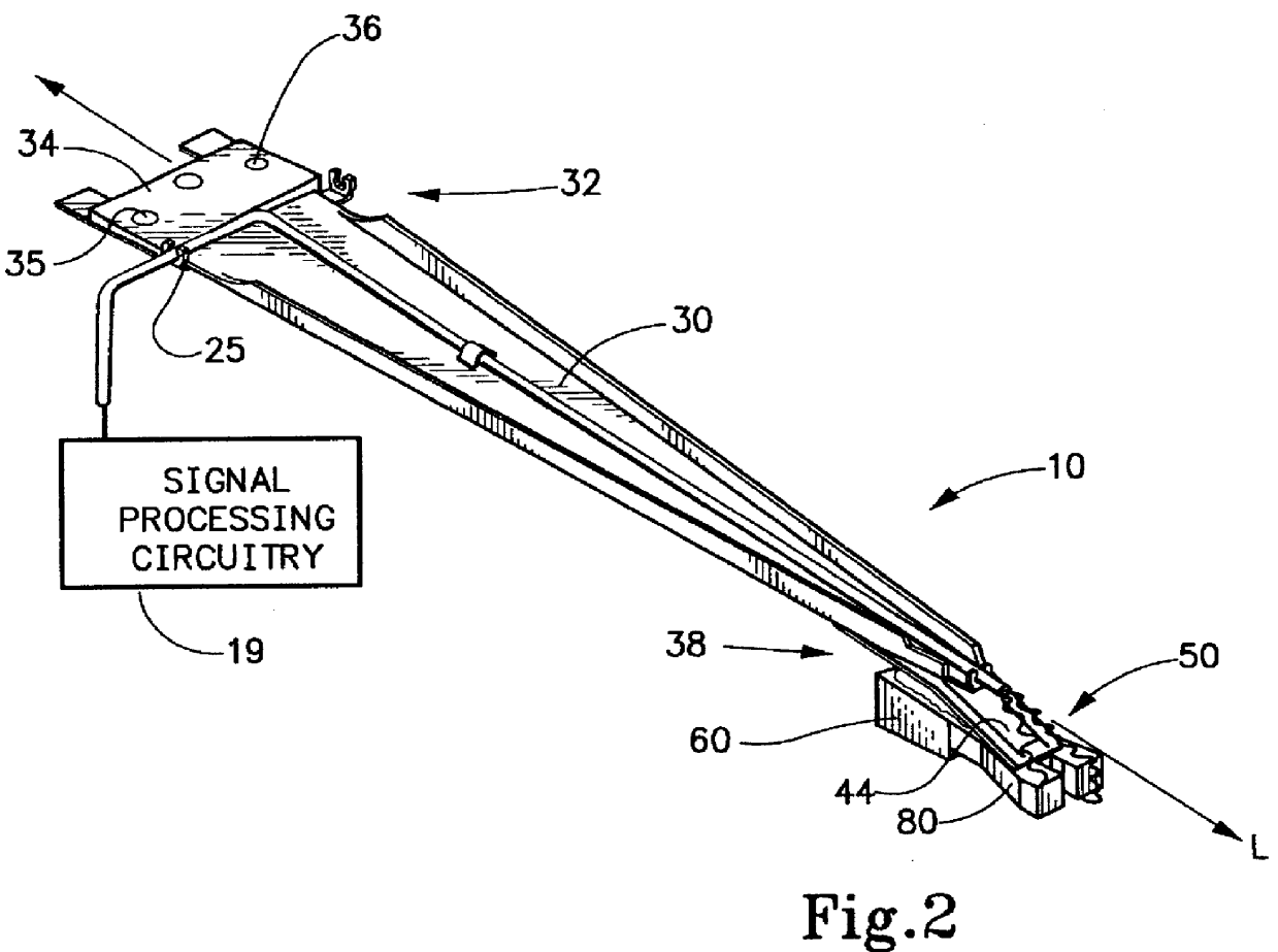
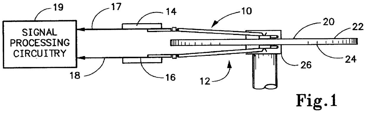
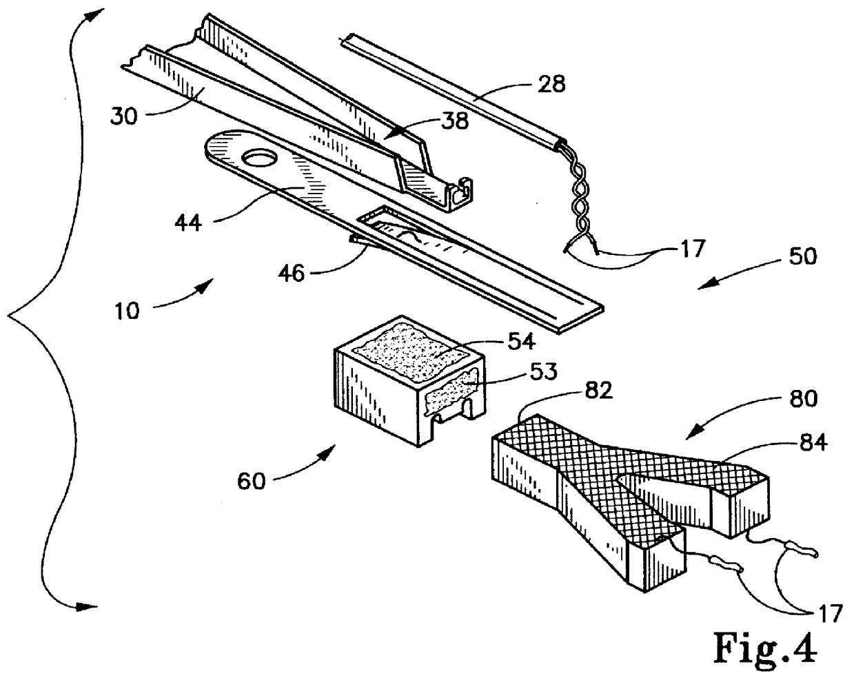
The present invention provides an improved slider construction for use in a glide head assembly that is operative with a test system to detect a presence of asperities on a moving surface. The invention relates to a glide head device, a glide head assembly, and a test device, each of which incorporates the improved slider construction. The slider of the present invention is less prone to structural degradation upon impact with an asperity during the detection process. While the invention will be described with reference to a slider having a pair of rails, it should be appreciated that the inventive concepts herein can be equally applied to other types of slider constructions. Moreover, while the slider is described in conjunction with a transducer in the form of a piezoelectric crystal, it should also be understood that other types of transducers, such as an acoustic emissions transducer, could also be employed without departing from the inventive concepts herein.

While the particula...


PUM

PropertyMeasurementUnit
obtuse angleaaaaaaaaaa
Raaaaaaaaaaa
Raaaaaaaaaaa

Abstract

A method is provided for fabricating a slider out of a production piece slider blank so that the slider may be used in a glide head assembly that is operative with a test system to detect a presence of asperities on a moving surface. Broadly, this method comprises configuring an air bearing structure on the production piece slider blank to form a working production piece having an unpolished air bearing surface and an outer sidewall surface which intersects the unpolished air bearing surface at a pheripheral edge. The unpolished air bearing surface is lapped to form a polished air bearing surface which is microfinished to a selected ABS Ra value. A region of the outer sidewall surface adjacent to the pheripheral edge is also lapped to form a sidewall margin area that is microfinished to a selected sidewall Ra value that is within a range of about ten times the selected ABS Ra value, thereby forming a finished production piece.

Description

The present invention is broadly directed to a glide head device adapted for use with a system for testing moving surfaces to detect a presence of asperities. More particularly, the present invention concerns an improved slider construction for use in a glide head device, which slider exhibits reduced structural degradation upon impact with an asperity. The present invention also relates to a test system which incorporates the improved slider construction and provides a method of fabricating the slider.In recent years, perhaps the most revolutionary development in technology has been the computer. While the fundamental components of a computer's architecture remain unchanged, the capabilities of these individual components have increased exponentially as technology rapidly progresses. Common to most every computer is a processing unit which receives input information and processes this information to generate an output. A computer program instructs the processing unit to perform var...

Claims


Application Information

Patent Timeline
Patent Type & Authority Patents(United States)
IPC IPC(8): G01B13/22G01B13/00G01B5/28G11B21/00G11B5/82G11B5/84G11B33/00G11B33/10
CPCG01B5/28G01B13/22G11B5/82G11B21/00G11B5/84Y10T29/49041Y10T29/49034Y10T29/49048Y10T29/49032Y10T29/49046G11B33/10
Inventor SMITH, JR., STANLEY C.
Owner MICROGLIDE
Why Eureka
Try Eureka