Winding wedge retention to maintain coil form
- Summary
- Abstract
- Description
- Claims
- Application Information
AI Technical Summary
Benefits of technology
Problems solved by technology
Method used
Image

Examples
Embodiment Construction
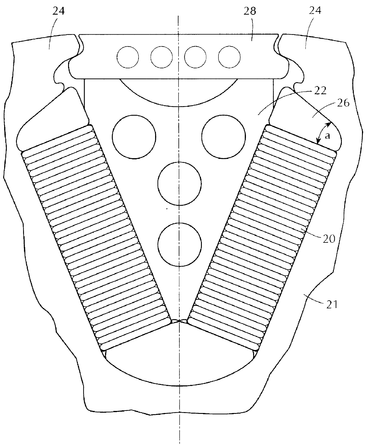
FIG. 3 schematically illustrates the coil (winding) retention system or scheme of the present invention. FIG. 3 illustrates and shows only a portion of a rotor 21 having a plurality of poles 24. As is well known, rotors typically include a plurality of poles, each of which is wound with coil conductors, called windings. For purposes of convenience, a single V-shaped cooling wedge positioned between two adjacent rotor poles is discussed. However, it will be understood that every rotor pole with the associated windings and wedges may embody the present invention.
As shown in FIG. 3, a coil winding 20 is retained by a V-shaped cooling wedge 22 and a dove tail-shaped wedge 26. For purposes of the present invention, wedge 22 is identified as a cooling wedge, such as disclosed in the above-mentioned U.S. Pat. No. 4,943,746. However, various rotors may not utilize its wedges for cooling purposes. Thus, the present invention is not limited to the utilization of cooling wedges and may easily ...
PUM
 Abstract
Description
Claims
Application Information
 - R&D
- Intellectual Property
- Life Sciences
- Materials
- Tech Scout
- Unparalleled Data Quality
- Higher Quality Content
- 60% Fewer Hallucinations
Browse by: Latest US Patents, China's latest patents, Technical Efficacy Thesaurus, Application Domain, Technology Topic, Popular Technical Reports.
© 2025 PatSnap. All rights reserved.Legal|Privacy policy|Modern Slavery Act Transparency Statement|Sitemap|About US| Contact US: help@patsnap.com