Dynamic filter system

a filter system and dynamic technology, applied in the direction of filtration separation, sedimentation settling tanks, separation processes, etc., can solve the problems of less rapid fouling of membranes, preferential fouling along inner radiuses, and increased fouling of membranes

Inactive Publication Date: 2000-09-12
PALL CORP
View PDF159 Cites 52 Cited by
  • Summary
  • Abstract
  • Description
  • Claims
  • Application Information

AI Technical Summary

Problems solved by technology

Thus, there is a problem of how to prevent fouling at the outer portion of the filter element and/or prevent back pressure damage to the inner radial portion of the filter element when the permeate outlet valve is fully or partially closed such that the permeate side pressure exceeds the process fluid side pressure produced along the inner radius.
However, the fouling of the membrane increases less rapidly than the increase in the flow rate due to the increased shear at the outer radius.
However, to the extent that the increased flow at the outer radius exceeds the increased shear, fouling occurs.
However, in some dynamic filter assemblies, e.g., spinning filters with out interleaved members, preferential fouling may occur along the inner radius.
Thus, while con

Method used


Image

  • Dynamic filter system
  • Dynamic filter system
  • Dynamic filter system

Examples


Embodiment Construction

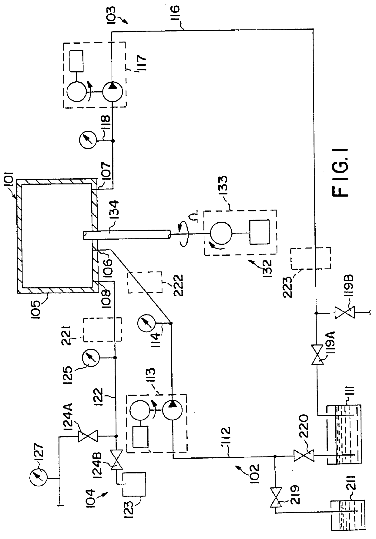
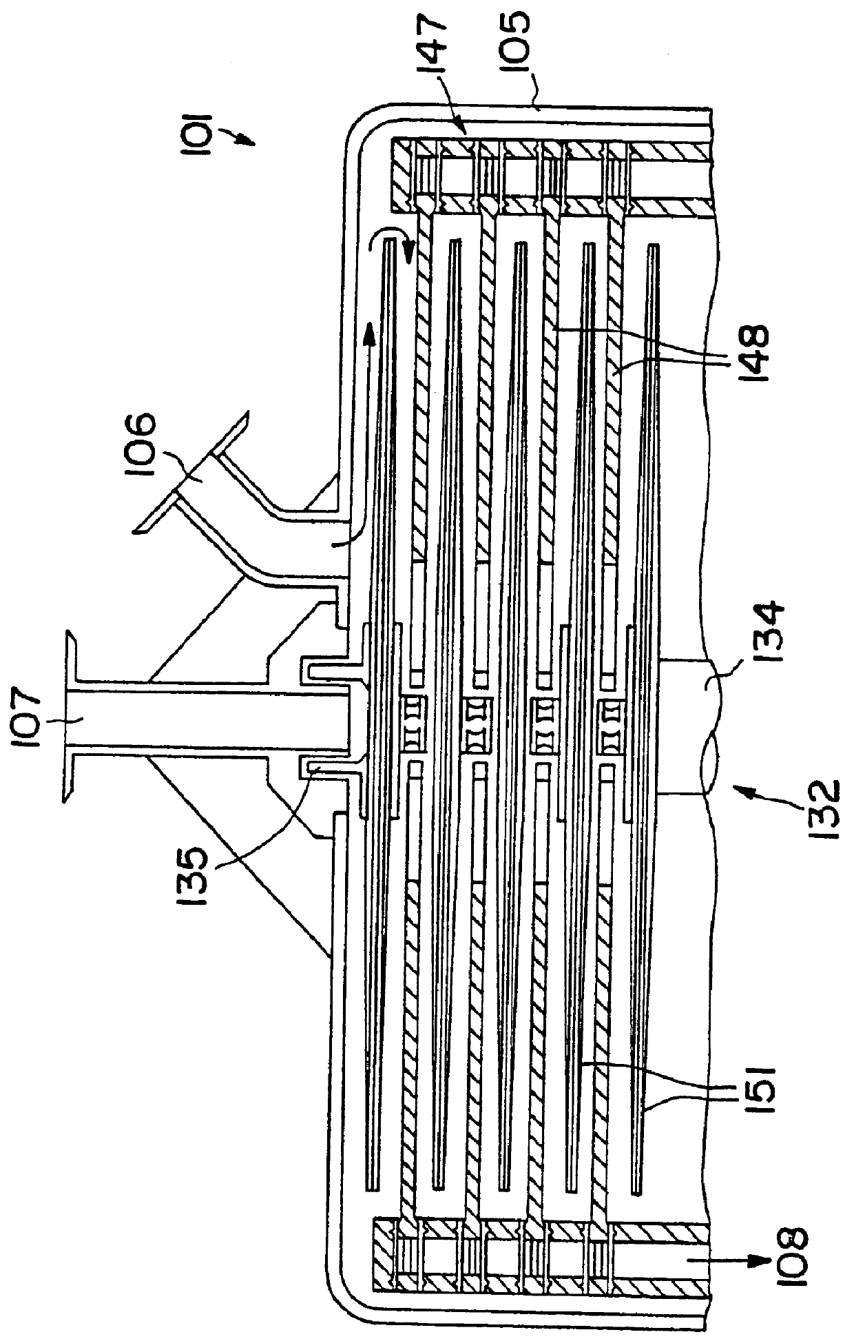
As shown in FIG. 1, a dynamic filter system of the present invention may include a dynamic filter assembly 101, a process fluid feed arrangement 102, a retentate recovery arrangement 103, and a permeate recovery arrangement 104. The dynamic filter assembly 101 generally comprises a housing 105 having a process fluid inlet 106, a retentate outlet 107, and a permeate outlet 108. The dynamic filter assembly 101 includes one or more filter elements and one or more members which are interleaved within the housing and arranged to rotate relative to one another.

The process fluid feed arrangement 102 is connected to the process fluid inlet 106 of the dynamic filter assembly 101 and may include a tank, vat, or other container 111 of process fluid which is coupled to the process fluid inlet 106 via a feed line 112. The process fluid feed arrangement 102 may also include a pump assembly 113 which can comprise a positive displacement pump in the feed line 112 for transporting the process fluid ...


PUM

PropertyMeasurementUnit
Pore sizeaaaaaaaaaa
Thicknessaaaaaaaaaa
Flow rateaaaaaaaaaa

Abstract

A dynamic filter system includes a dynamic filter assembly including one or more filter elements and one or more members disposed within a housing. The filter elements and the members are interleaved and arranged to rotate with respect to one another. The dynamic filter assembly preferably includes one or more mechanisms to prevent preferential fouling.

Description

The present invention relates to a dynamic filter assembly and, in particular, to an improved dynamic filter assembly and filter unit.A dynamic filter assembly typically includes a housing which contains a filter unit having one or more filter elements positioned adjacent to an element having one or more members. In typical embodiments, there is a relative motion between the filter elements and the members, e.g., rotational motion. The filter elements and the members may have any of a variety of suitable configurations. For example, the filter unit may include a stack of substantially flat, disk-shaped filter elements while the element may include a stack of substantially flat rotary disks or members coupled to a shaft. The rotary disks may be interleaved between the filter elements with a gap maintained between each filter element and rotary disk. The rotary disks preferably rotate relative to the filter elements.In typical embodiments, a process fluid is input into the housing thr...

Claims


Application Information

Patent Timeline
IPC IPC(8): B01D65/08B01D63/16B01D65/00B01D63/08
CPCB01D63/084B01D63/16B01D65/00B01D65/08B01D2321/2008
Inventor MILLER, JOHN D.GEIBEL, STEPHEN ARTHURHURWITZ, MARK FRANCISFENDYA, THOMAS J.ALEX, TONY
Owner PALL CORP
Why Eureka
Try Eureka