Electric submersible pump with hollow drive shaft

Inactive Publication Date: 2000-09-19
SAUDI ARABIAN OIL CO
View PDF13 Cites 43 Cited by
  • Summary
  • Abstract
  • Description
  • Claims
  • Application Information

AI Technical Summary

Problems solved by technology

Electric submersible pumps installed in-line on well tubing strings present problems in well monitoring and treatment.
Wire line tools, coiled tubing and other devices cannot be lowered to the production interval below the pump due to the p

Method used


Image

  • Electric submersible pump with hollow drive shaft

Examples


Embodiment Construction

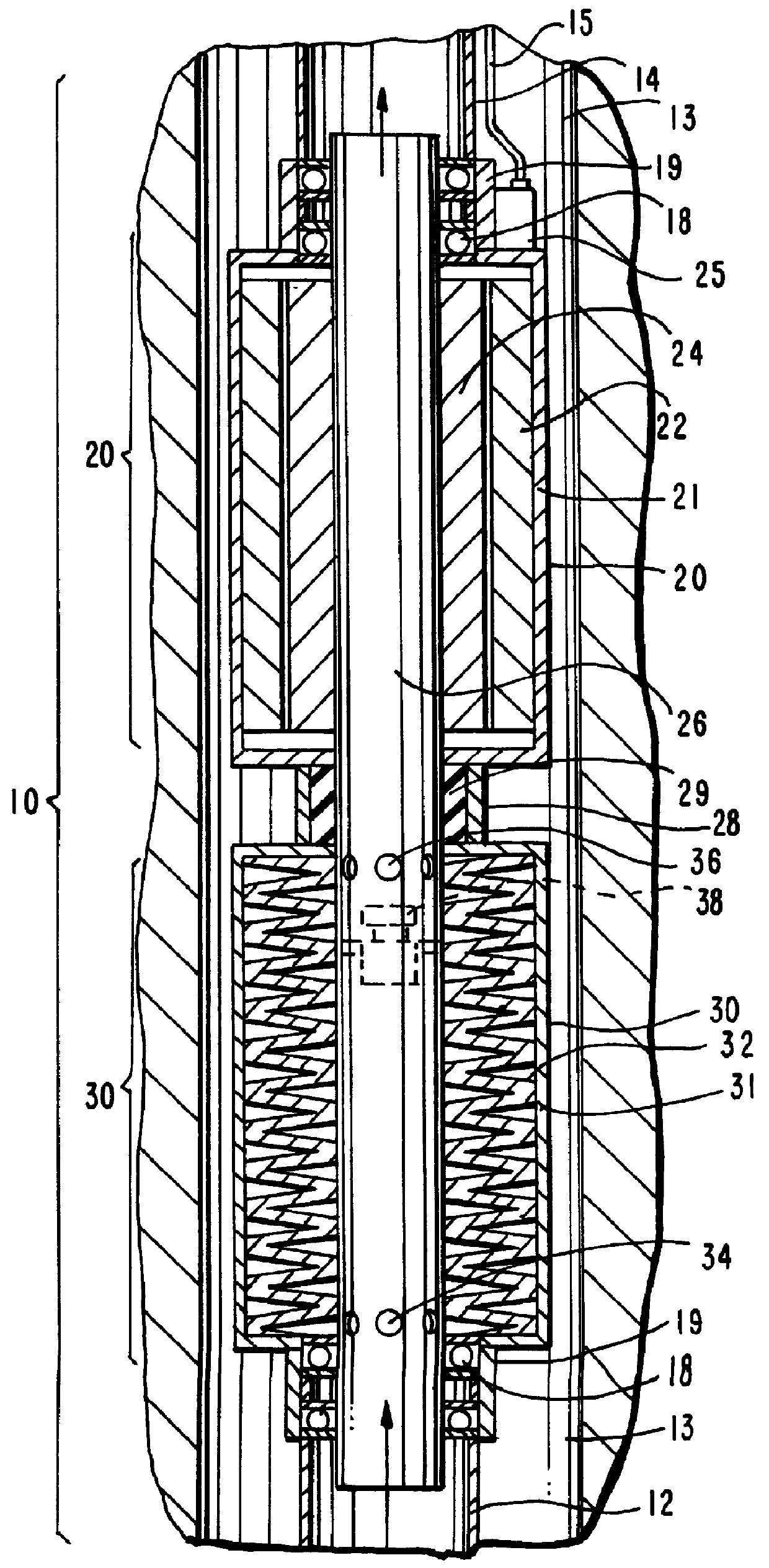
The drawing depicts a first section 12 of a vertical well pipe or tubing string, (such as that used in an oil well), that has been assembled with an electric submersible pump 10 of the invention. The electric submersible pump is comprised of two principal elements, these being the drive motor 20 and the pump 30. The drive motor 20 is comprised of an annular stator 22 and a concentric rotor 24 that is secured to hollow drive shaft 26. The lower or upstream end of drive shaft 26 is attached to annular pump impellers 32 and includes lower intake ports 34 and upper discharge ports 36. As schematically illustrated, drive shaft 26 is preferably of one-piece construction for reasons of simplicity and economy. Alternatively, shaft 26 can be constructed of separate motor and pump drive shafts that are joined by an appropriate coupling (not shown.)

Positioned on the interior of hollow shaft 26 is check valve or plug 38. The plug serves as a one-way valve against the back-pressure of the fluid ...


PUM


Abstract

A combined electric motor and submersible pump apparatus intended for installation in line with the well tubing has a hollow drive shaft the down stream end of which is secured to the rotor of the motor and mounted for rotation in axial alignment with the axis of the tubing, the pump impellers being mounted on the upstream end of the hollow shaft, the shaft also having inlet and discharge ports and a check valve mounted on the interior of the drive shaft that is closed when the pump is activated. When the check valve is in the open position, a wire line tool or the like can be passed through the hollow drive shaft to a position below the apparatus.

Description

The invention relates to electric submersible pumps for use in well tubing, for example, in oil field well bores.BACKGROUND OF INVENTIONElectric submersible pumps installed in-line on well tubing strings present problems in well monitoring and treatment. Wire line tools, coiled tubing and other devices cannot be lowered to the production interval below the pump due to the presence of the pump / motor assembly in the well bore.In order to permit passage of wire line tools and the like, Y-shaped bypass pump assemblies have been developed. However, these bypass assemblies can only be accommodated in well casings that are substantially larger than the standard oil casings presently employed in oil fields throughout the world. The cost of retrofitting a well with the 95 / 8" casing required to install a Y-shaped bypass assembly is estimated to be approximately one million dollars.It is therefore one principal object of this invention to provide an electric submersible pump that can be instal...

Claims


Application Information

Patent Timeline
IPC IPC(8): F04D13/10F04D13/06
CPCF04D13/10
Inventor AL-TOWAILIB, ABDULAZEEM ABBAS
Owner SAUDI ARABIAN OIL CO
Why Eureka
Try Eureka