Method and apparatus for multi-level demand caching of textures in a graphics display device

a graphics display device and texture technology, applied in static indicating devices, memory adressing/allocation/relocation, instruments, etc., can solve the problems of limiting the graphics capabilities of the graphics display device, increasing the complexity of cpu processing, and suffering from its own disadvantages

Inactive Publication Date: 2000-10-10
INTEL CORP
View PDF12 Cites 50 Cited by
  • Summary
  • Abstract
  • Description
  • Claims
  • Application Information

AI Technical Summary

Problems solved by technology

However, while this architecture provides a speedier access to textures stored in the graphics accelerator 140, it suffers from several disadvantages.
It requires the CPU 110 to actually download the particular texture for use by the graphics accelerator 140, which increases the complexity of CPU processing.
Furthermore, because the size of the texture memory 160 is constrained by the total system cost, the "push" architecture limits the amount of textures that can be used by the application running on the CPU 110, thereby limiting the graphics capabilities of the graphics display device.
While this architecture alleviates the complexity of the CPU processing and allows the CPU's application to use more texture than it otherwise could have in the "push" architecture, it also suffers from its own disadvantages.
As previously mentioned, a drawback to using the main memory 130 is that its retrieval rate is significantly slower than the retrieval rate of the "push" architecture's local texture memory 160.
As a result, the computer system's graphics performance is adversely impacted by the slower retrieval of these textures from the main memory 130.
However, while large-capacity high-speed memory is available, it is quite expensive.
And, using such memory could easily double the cost of the computer, thereby placing the personal computer out of reach (from a monetary standpoint) for a number of people for which it was originally intended.

Method used


Image

  • Method and apparatus for multi-level demand caching of textures in a graphics display device
  • Method and apparatus for multi-level demand caching of textures in a graphics display device
  • Method and apparatus for multi-level demand caching of textures in a graphics display device

Examples


Embodiment Construction

The following examples are included to demonstrate preferred embodiments of the invention. It should be appreciated by those of skill in the art that the techniques disclosed in the examples that follow represent techniques discovered by the inventor to function well in the practice of the invention, and thus can be considered to constitute preferred modes for its practice. However, those of skill in the art should, in light of the present disclosure, appreciate that many changes can be made in the specific embodiments which are disclosed without departing from the spirit and scope of the invention.

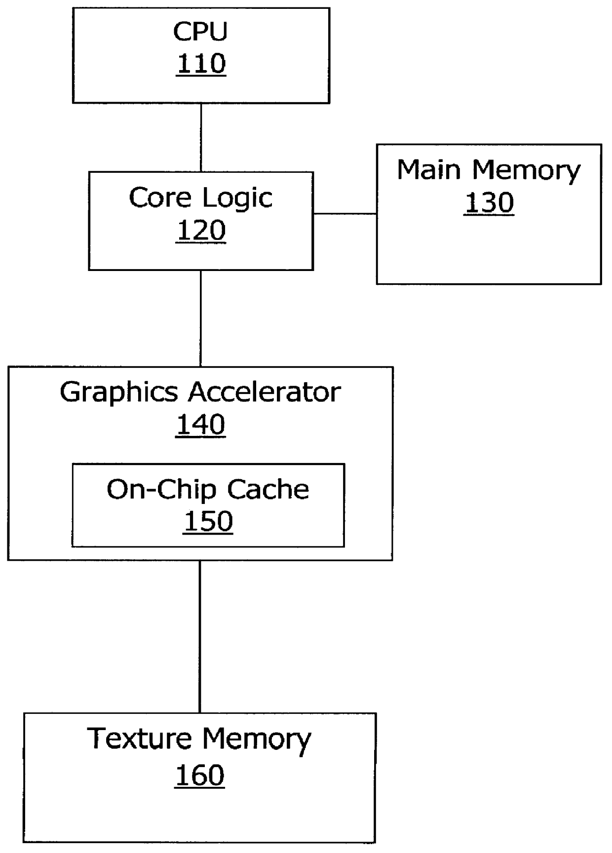
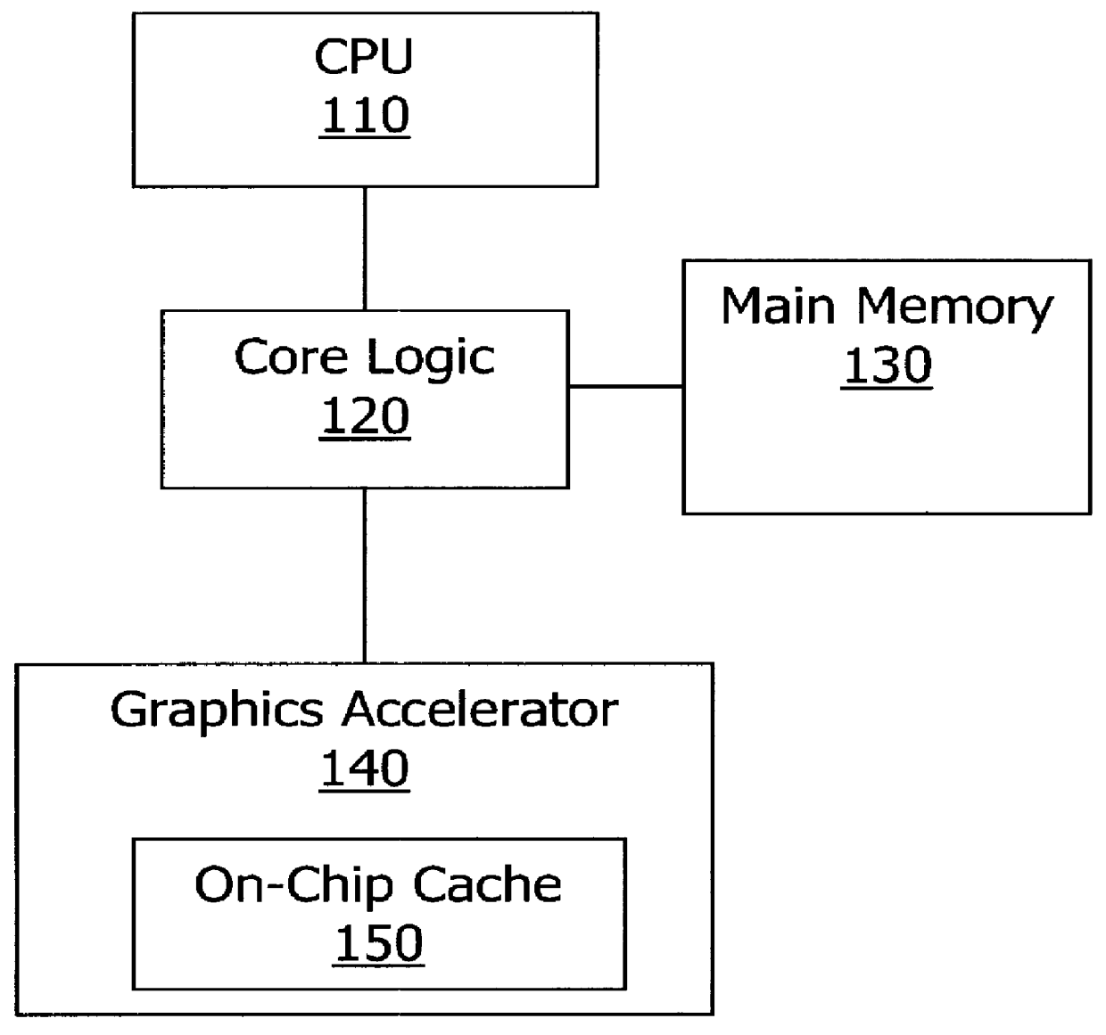
Turning now to FIG. 2A of the drawings, a block diagram of a computer graphics architecture 200 for demand caching of textures is shown. A CPU 210, which has a computer graphics application running thereon, generates a series of primitives for display on a graphics display device (not shown). Generally, these primitives are three-dimensional polygons that provide the framework of the disp...


PUM


Abstract

A computer graphics system for caching textures includes an L3 memory, an L2 cache, and an L1 cache for storing such textures and also includes a graphics accelerator (GA) for mapping these stored textures onto primitives for graphics display. The L3 memory, which has the largest capacity also has the slowest retrieval speed, while the L1 cache has the smallest capacity and the quickest retrieval speed. The textures are divided into a plurality of L2 texture blocks and each L2 texture block is subdivided into a plurality of L1 sub-blocks. During its rendering process, the GA searches the L1 cache for a particular L1 sub-block that is to be applied to a primitive. If such L1 sub-block is stored within the L1 cache, the GA will extract the desired texels (i.e., texture pixels) from the L1 sub-block and apply such texels to the primitive. If the L1 sub-block is not located in the L1 cache, the GA will search the L2 cache for the L1 sub-block. If it is found in the L2 cache, the GA will load the L1 sub-block to the L1 cache. However, if the L1 sub-block is not found within the L2 cache, the GA will load the L1 sub-block from the L3 memory to both the L1 and L2 caches. Advantageously, when the GA requires such L1 sub-block again, the GA will have a speedier access to the L1 sub-block via the L1 and L2 caches.

Description

1. Field of the InventionThe present invention relates generally to computer graphics architecture and, more particularly, to a method and apparatus for multi-level demand caching of texture images for mapping on geometrical primitives in a graphics display device.2. Description of the Related ArtPrior art graphics display devices have the ability to display three-dimensional polygons (i.e., primitives) with texture images mapped on these polygons. These texture images give the computer graphics a realistic or life-like appearance. For example, a texture image may be a picture of a brick facade for application to a three-dimensional polygon representing the framework of a house. Or, alternatively, the texture image may be of a wood grain texture applied to a primitive that forms the shape of a desk. To improve the realism of these graphics, a greater variety of these texture images is desirable. And, consequently, more computer memory is required to store this growing collection of ...

Claims


Application Information

Patent Timeline
Patent Type & Authority Patents(United States)
IPC IPC(8): G06F12/08G06T1/60
CPCG06F12/0875G06T1/60G06F12/0897
Inventor COX, MICHAEL BRIANSHANTZ, MICHAEL J.
Owner INTEL CORP
Why Eureka
Try Eureka