
Method and apparatus for managing and accessing depth data in a computer graphics system

a depth buffer and depth data technology, applied in the field of graphics processing systems, can solve the problems of limiting the performance of the system, affecting the performance of the graphics processing unit, and affecting the performance of the graphics processing unit, and achieve the effect of improving the performance of the graphics system

Inactive Publication Date: 2005-11-01
NVIDIA CORP
View PDF1 Cites 108 Cited by
  • Summary
  • Abstract
  • Description
  • Claims
  • Application Information

AI Technical Summary

Benefits of technology

[0011]It is an object of the present invention to provide an improved method and apparatus for managing depth data in a graphics display system so that performance of the graphics system is not limited by the time required to access the depth data.
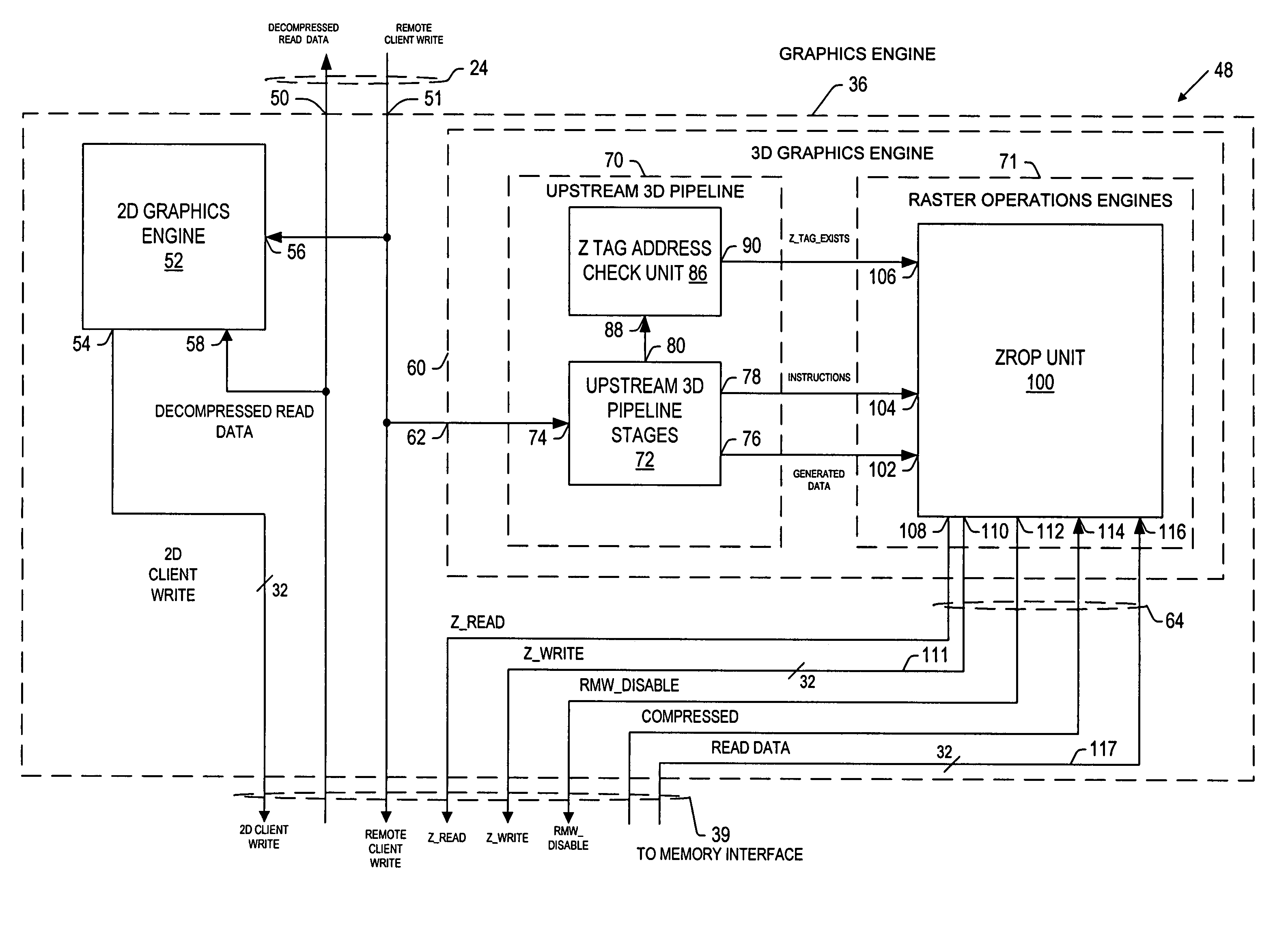
[0012]Briefly, a presently preferred embodiment of the present invention provides a computer graphics system for processing image data including Z data for use in displaying three dimensional images on a display unit. The system includes: a depth buffer providing for temporary storage of Z data; and a graphics processing unit having a graphics engine for generating image data including Z data, and a memory interface unit communicatively coupled to the graphics engine and communicatively coupled to the depth buffer via a depth buffer interface. The graphics processing unit is operative to compress at least a portion of the generated Z data, to write the compressed portion of Z data to the depth buffer via the depth buffer interface in a compressed format, to read portions of compressed Z data from the depth buffer via the depth buffer interface, and to decompress the compressed Z data read from the buffer. An advantage of the present invention is that effective Z data bandwidth through the depth buffer interface is maximized in order to facilitate fast depth buffer access operations.

Problems solved by technology

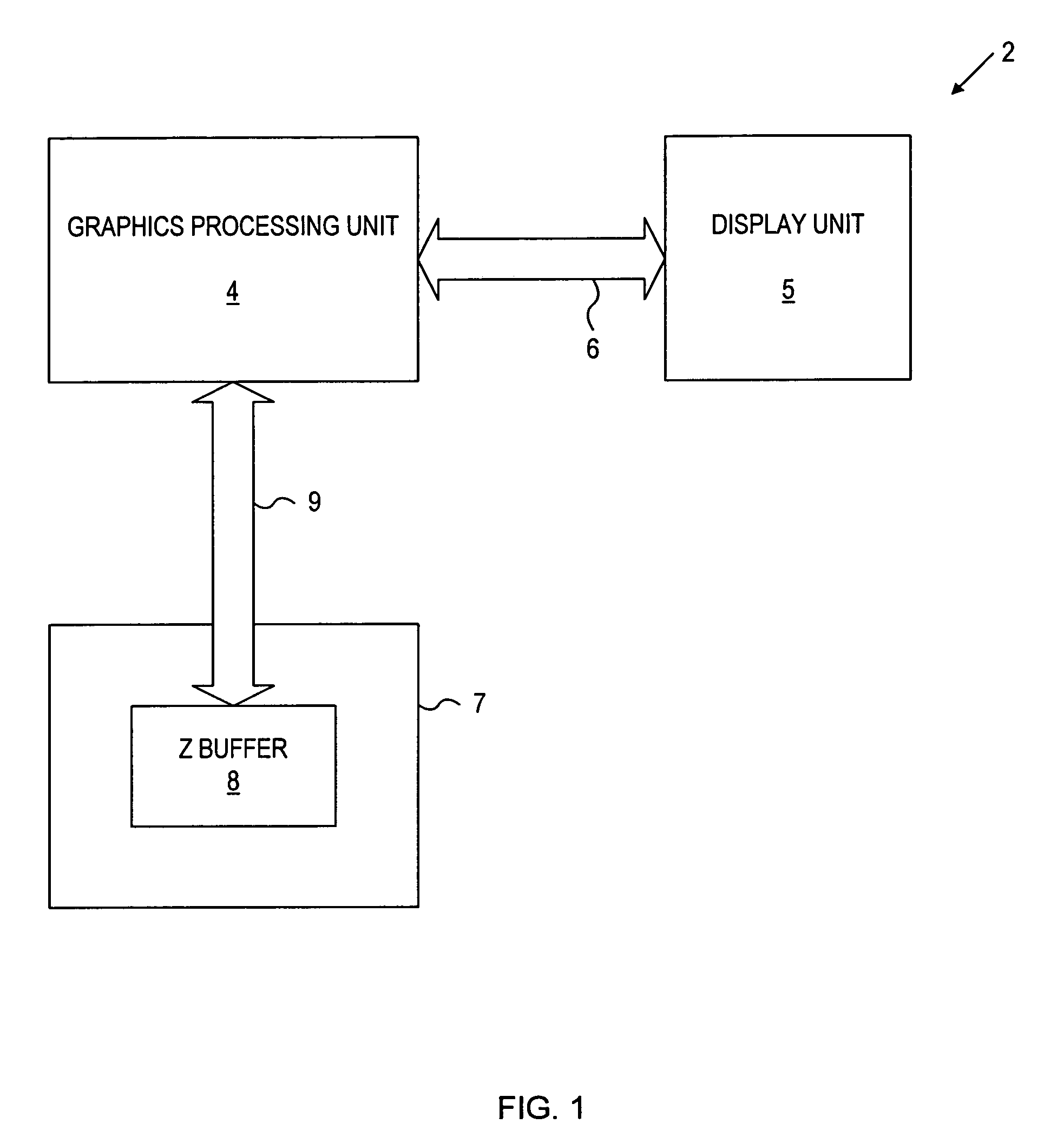
The bandwidth limitation of the interface 9 imposes a limit on the performance of the system because the graphics pipeline generates and compares Z data faster than the Z data can be accessed.
However, this solution is not feasible because silicon real estate in the graphics processing unit 4 is very limited and very expensive.

Method used


Image

  • Method and apparatus for managing and accessing depth data in a computer graphics system
  • Method and apparatus for managing and accessing depth data in a computer graphics system
  • Method and apparatus for managing and accessing depth data in a computer graphics system

Examples


Embodiment Construction

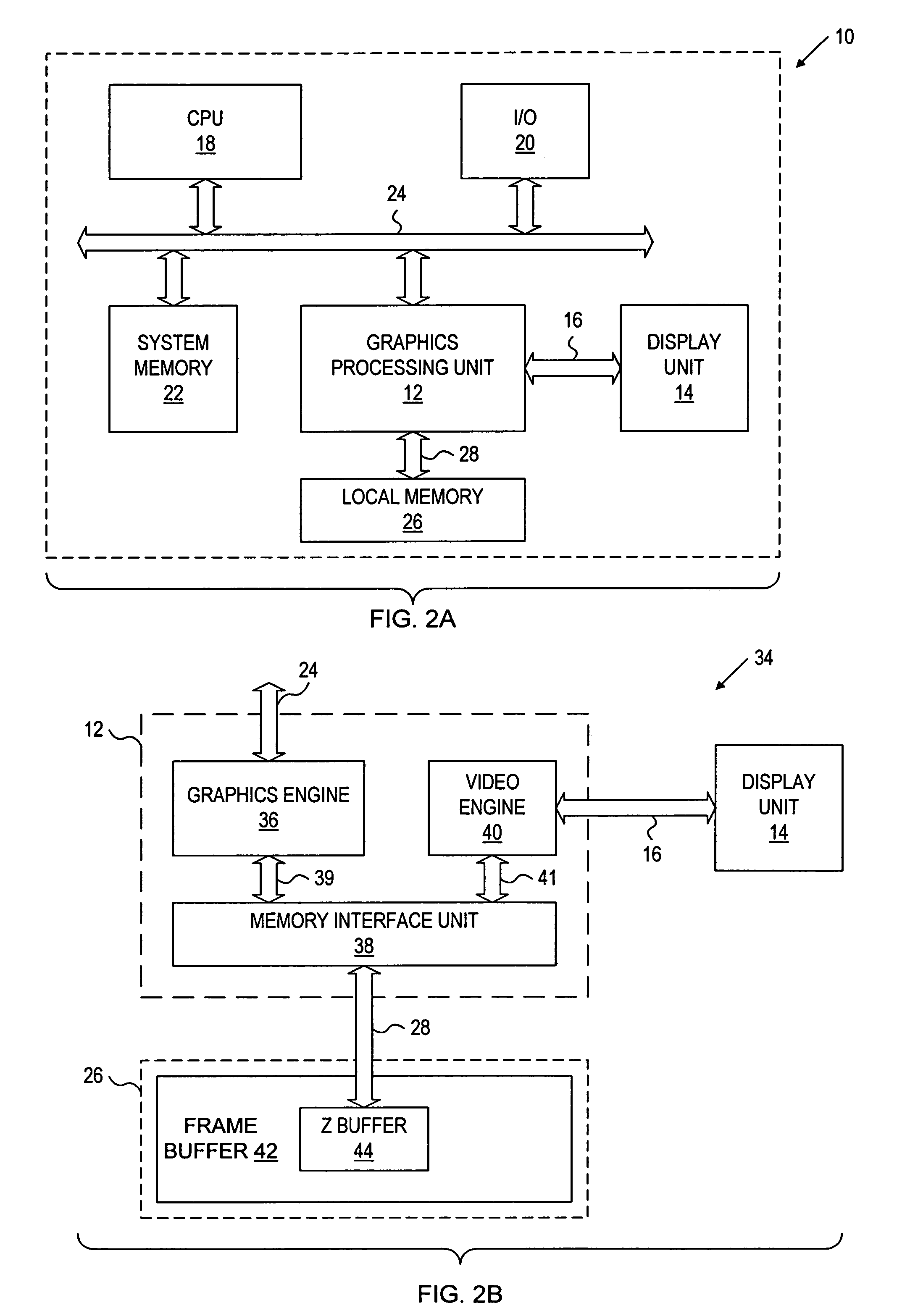
[0036]FIG. 2A shows a generalized block diagram illustrating a computer graphics system at 10 including: a graphics processing unit 12 in accordance with the present invention; a display unit 14 coupled with unit 12 via an interface 16; a central processing unit 18, an input / output unit 20, and a system memory unit 22 each being coupled with the unit 12 via a system bus 24; and a local memory unit 26 communicatively coupled with the graphics processing unit 12 via a local memory interface 28. In operation, the graphics processing unit 12 receives image display instructions and image data from clients such as the CPU 18 via the system bus 20, and executes the instructions resulting in the storage of image data in the local memory unit 26. The graphics processing unit 12 also provides for scanning image data from the frame buffer 42.

[0037]FIG. 2B shows a schematic block diagram illustrating further details of the graphics processing unit 12 (FIG. 1) at 34 in accordance with the presen...


PUM


Abstract

A computer graphics system provides for processing image data including Z data for use in displaying three-dimensional images on a display unit. The system includes: a depth buffer providing for temporary storage of Z data; and a graphics processing unit having a graphics engine for generating image data including Z data, and a memory interface unit communicatively coupled to the graphics engine and communicatively coupled to the depth buffer via a depth buffer interface. The graphics processing unit is operative to compress at least a portion of the generated Z data, to write the compressed portion of Z data to the depth buffer via the depth buffer interface in a compressed format, to read portions of compressed Z data from the depth buffer via the depth buffer interface, and to decompress the compressed Z data read from the buffer. An advantage of the present invention is that effective Z data bandwidth through the depth buffer interface is maximized in order to facilitate fast depth buffer access operations.

Description

BACKGROUND OF THE INVENTION[0001]1. Field of the Invention[0002]The present invention relates generally to graphics processing systems, and more specifically to an improved method and apparatus for managing the storage of depth data in a depth buffer of a graphics processing system.[0003]2. Description of the Prior Art[0004]FIG. 1 shows a generalized block diagram illustrating a typical prior art computer graphics system at 2 generally including: a graphics processing unit 4; a display unit 5 coupled with the graphics processing unit 4 via an interface 6; and a local memory unit 7 communicatively coupled with the graphics processing unit, the local memory unit providing temporary storage of image data for displaying a 3-dimensional (3-D) image on the display unit. The local memory unit 7 includes: a refresh buffer (not shown) for storing intensity values for each of a plurality of (x, y) pixel positions on the display unit 5; and at least one depth buffer, or Z buffer, 8 coupled wit...

Claims


Application Information

Patent Timeline
Patent Type & Authority Patents(United States)
IPC IPC(8): G06T15/40G06T15/10
CPCG06T15/405
Inventor VAN DYKE, JAMES M.MARGESON, III, JAMES E.
Owner NVIDIA CORP
Learn More