Utility knife

a technology of utility knives and blades, applied in the field of utility knives, can solve the problems of affecting the safety of users, and affecting the safety of users

Inactive Publication Date: 2000-10-17
REDDIG
View PDF5 Cites 25 Cited by
  • Summary
  • Abstract
  • Description
  • Claims
  • Application Information

AI Technical Summary

Benefits of technology

to provide a utility knife with a rapid interlock mechanism which assures the required rigidity of the interlocked shells in forming a hollow handle for holding an exchangeable blade;
to construct the interlock in such a way that blades may be rapidly exchanged without any danger;
Preferably, the latching member is made of a spring elastic material that on the one hand is stiff enough to hold the two shells together and to hold the blade in place in an interlocked position, while at the same time readily yielding to a lifting of the operating member for disconnecting the two shells from each other to the extent that they can be sufficiently opened for a blade insertion or blade exchange.
It is an advantage of the invention that the operating member does not interfere with holding the knife handle formed by the shells. A further important advantage is seen in that the operating member cannot accidentally release itself because when the knife is held by the operator, the operator's hand securely holds the operating member in its recess.

Problems solved by technology

The blades are subject to heavy wear and tear and thus must be frequently replaced.
The loose storage of blades which are quite sharp, inside the hollow handle may be dangerous, especially when changing a blade.
However, a screw connection once tightened is not necessarily readily releasable even if the screw has a knurled head so that using a tool may become necessary.
Additionally, unscrewing the shells from each other and then again screwing the shells together takes time and is not efficient.
Thus, the protruding screw head interferes with properly holding the knife, especially when the diameter of the screw head is larger than the cross-sectional width of the shell handle.
Such diameter is desirable for operating the screw but not necessarily convenient for handling or rather holding the knife handle.

Method used


Image

  • Utility knife
  • Utility knife
  • Utility knife

Examples


Embodiment Construction

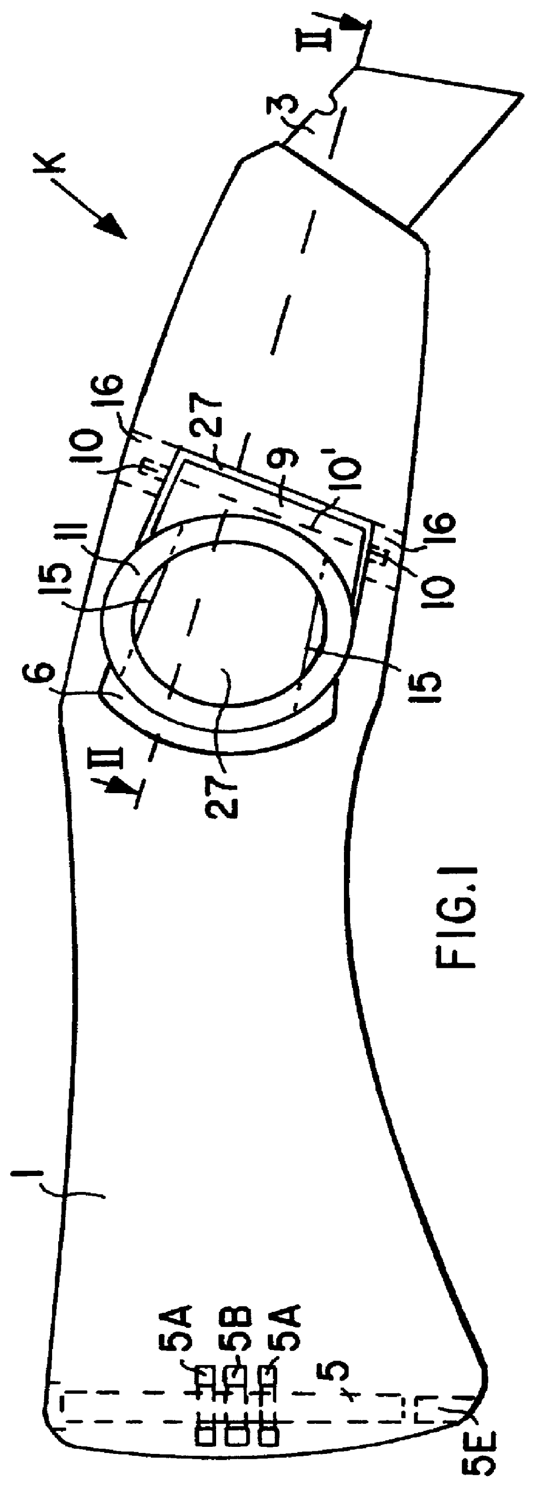
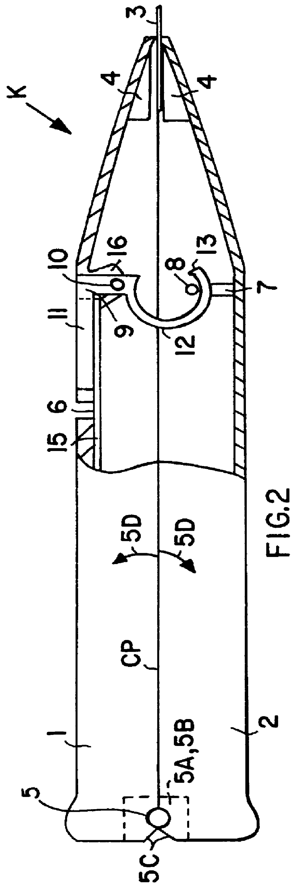
FIGS. 1 and 2, viewed in conjunction, show a utility knife K having two shells 1 and 2. Shell 2 is referred to as one shell, while shell 1 is referred to as the other shell. Both shells 1 and 2 are hinged to each other at one end by a hinge pin 5 passing through hinge elements 5A and 5B rigidly secured to the inner surface of the respective shell. The shell end walls are beveled at 5C to permit a sufficient opening of the shells as indicated by the arrows 5D for exchanging a blade 3 mounted in a blade mounting 4 at the opposite end of the knife K. Preferably, one of the hinge blocks 5B is secured to one inner surface of one shell while the other two hinge blocks 5A are an integral part of the molded other shell, whereby these blocks project mutually into the other shell and one block is positioned between the two other blocks in the closed position of the shells. The holes in the hinge blocks receive the hinge pin 5. The hinge pin is preferably inserted with a spring elastic fit so ...


PUM


Abstract

A utility knife has two shells that are pivoted or hinged to each other at one end to permit opening the knife handle formed by the shells for insertion or replacement of a knife blade. The two shells are interlocked with each other by a latching mechanism, including a stationary section in one shell and a rotatable section in the other shell. The rotatable section has a spring elastic bail that engages the stationary section and an operating member for disengaging or engaging the rotatable member from the stationary stop bar. In the interlocking position the operating member is recessed in a recess in the surface of one of the shells. When the knife is used, the operator's hand provides additional safety by keeping the operating member in its recess and thus the two shells interlocked.

Description

The invention relates to utility knives with replaceable or exchangeable blades. Such knives are used for cutting flat materials such as floor coverings, paper or the like.BACKGROUND INFORMATIONUtility knives are conventionally formed of two shells that are hollow and are hinged to each other to form a hollow handle. The hinge is usually provided at one end of the two shells while a blade mounting is arranged at the opposite end. The blade mounting holds a knife blade so that it partially protrudes from the handle. The two shells are normally interlocked after a blade has been inserted into the blade mounting so that an unintended opening of the knife is prevented.The blades are subject to heavy wear and tear and thus must be frequently replaced. It is necessary to open the knife handle for the blade exchange, whereupon the two shells must again be interlocked to form the hollow handle in which spare blades and / or used blades may be stored. The loose storage of blades which are quit...

Claims


Application Information

Patent Timeline
IPC IPC(8): B26B5/00
CPCB26B5/005
Inventor REDDIG, BERND
Owner REDDIG
Why Eureka
Try Eureka