Fracturing apparatus

a technology of fracturing apparatus and fracturing chamber, which is applied in the direction of metal-working apparatus, thin material processing, metal-working apparatus, etc., can solve the problems of difficult control of quality and yield of pv cells, uneven cracks frequently formed on the pv cell, and melting regions near the cut surface of the pv cell, etc., to achieve easy control of quality, yield and capacity of the divided substra

Inactive Publication Date: 2013-11-19
RYTEC CORP
View PDF11 Cites 7 Cited by
  • Summary
  • Abstract
  • Description
  • Claims
  • Application Information

AI Technical Summary

Benefits of technology

[0027]With such a design, the fracturing apparatus including the first suction device, the second suction device, and the cylinder operates automatically to fracture the substrate. As a result, the cut surfaces of the two portions of the substrate are smooth. Therefore, uneven cracks do not easily form on the substrate. Furthermore, when utilizing the fracturing apparatus to fracture a large number of substrates, the quality, yield and capacity of the divided substrates are easy to control.

Problems solved by technology

However, when a laser directly cuts a PV cell into two sections, the regions near the cut surfaces of the PV cell may melt and be short-circuited as a result of the significant heat generated during the cutting process.
Because the material of the PV cell is brittle and different operators may apply different forces during such a fracturing process, uneven cracks frequently are formed on the PV cell.
Moreover, the quality and yield of the PV cells are difficult to control.
Therefore, uneven cracks do not easily form on the substrate.

Method used


Image

  • Fracturing apparatus
  • Fracturing apparatus
  • Fracturing apparatus

Examples


Embodiment Construction

[0035]In the following detailed description, for purposes of explanation, numerous specific details are set forth in order to provide a thorough understanding of the disclosed embodiments. It will be apparent, however, that one or more embodiments may be practiced without these specific details. In other instances, well-known structures and devices are schematically shown in order to simplify the drawings.

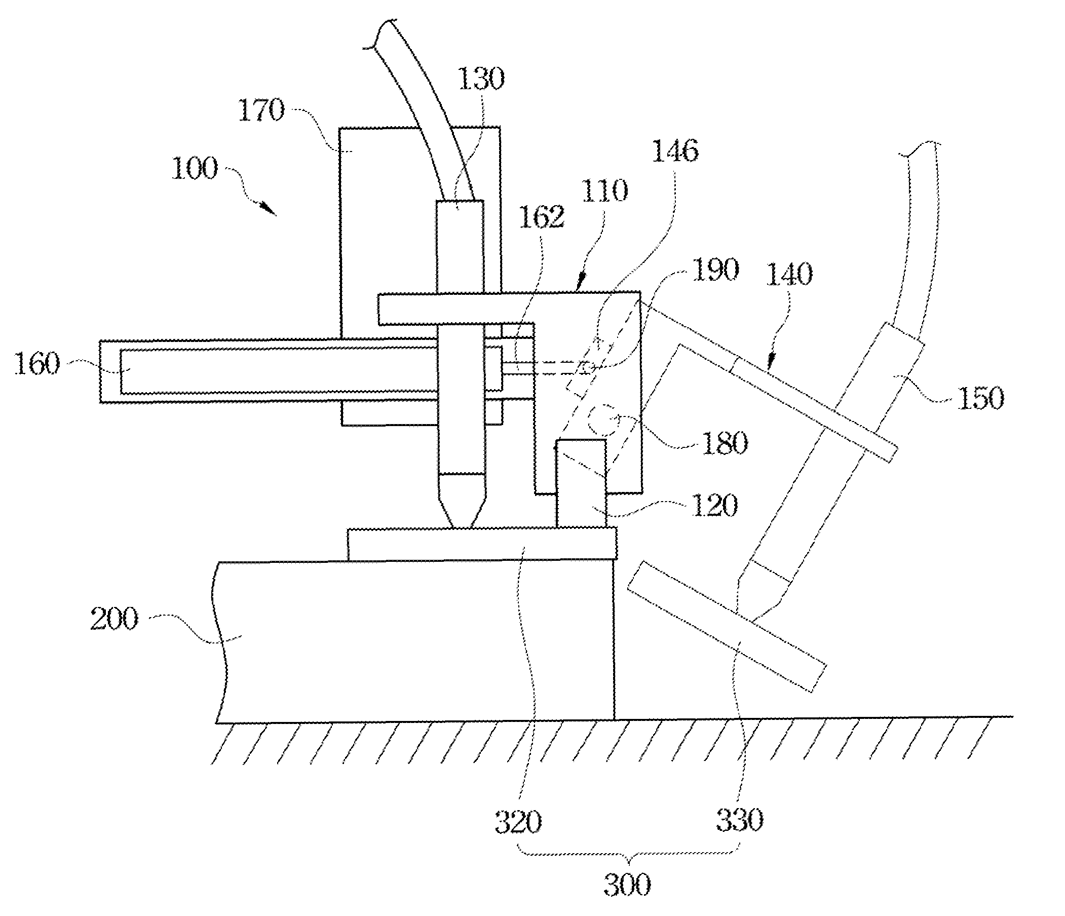
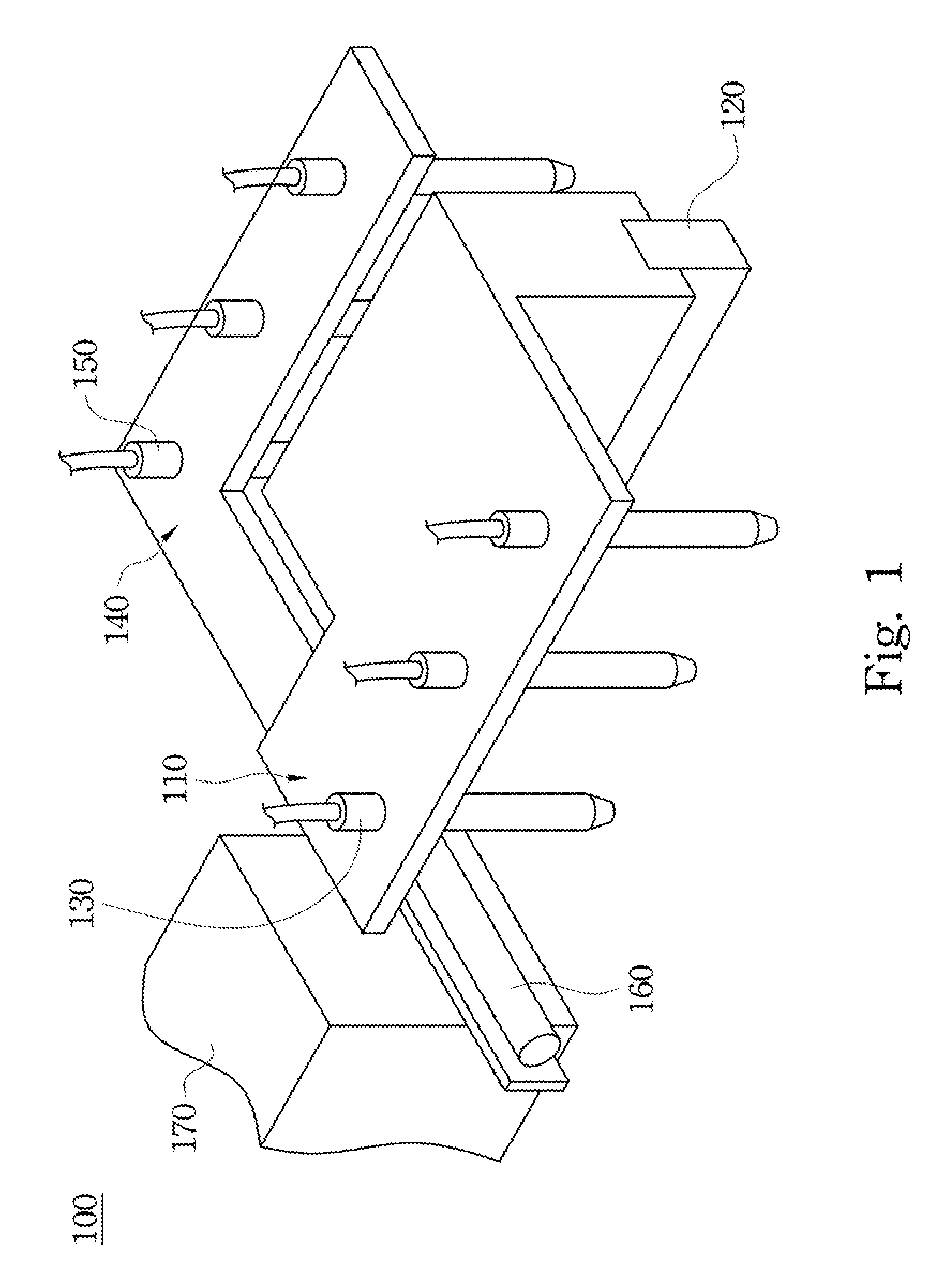
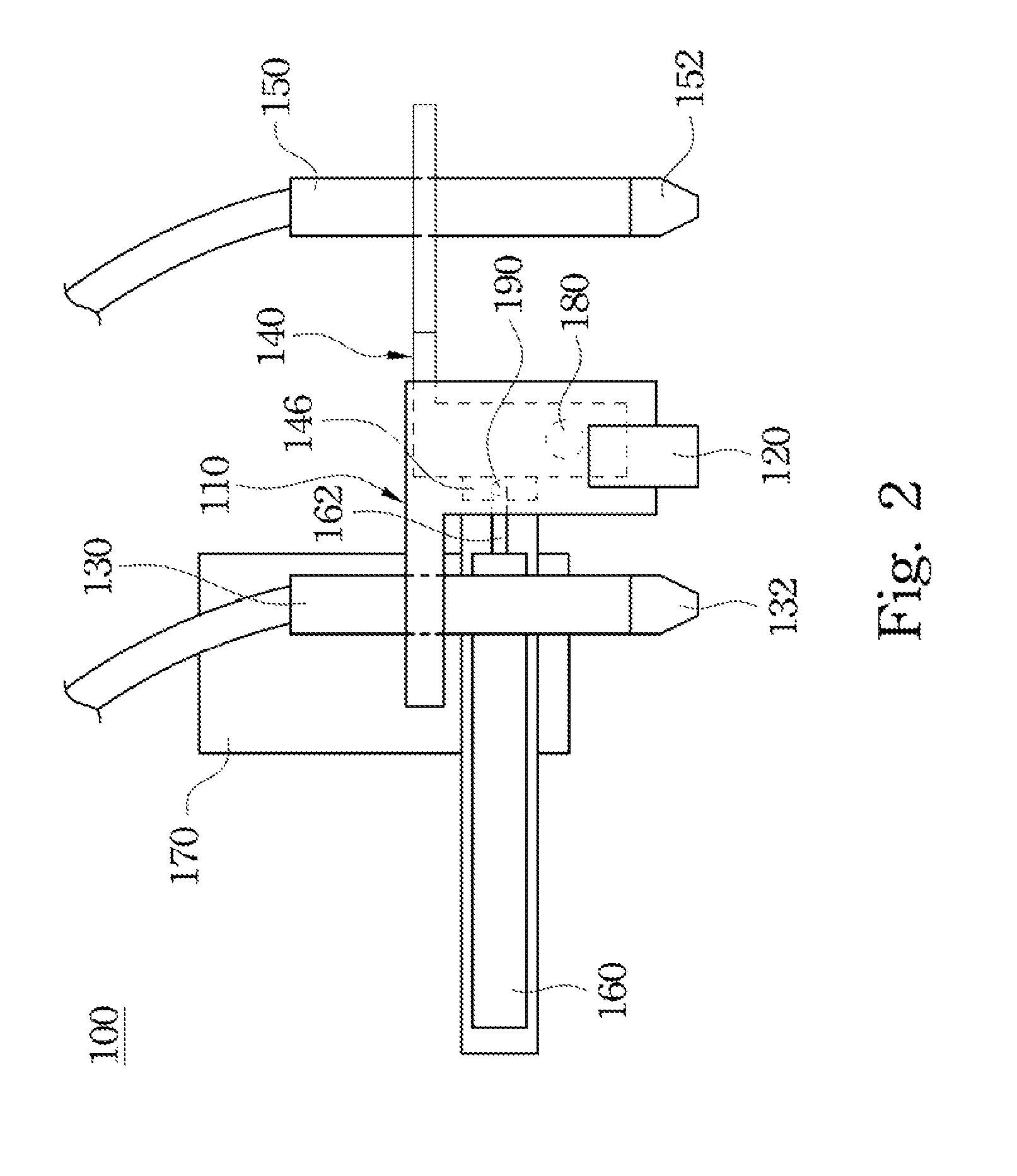
[0036]FIG. 1 is a perspective view of a fracturing apparatus 100 of an embodiment of the present invention. FIG. 2 is a side view of the fracturing apparatus 100 shown in FIG. 1. FIG. 3 is a top view of the fracturing apparatus 100 shown in FIG. 1. As show in FIG. 1 to FIG. 3, the fracturing apparatus 100 includes a first board portion 110, a pressing element 120, a first suction device 130, a second board portion 140, a second suction device 150, and a cylinder 160. The first suction device 150 is secured to the first board portion 110. The second board portion 140 is rotatably co...


PUM


Abstract

A fracturing apparatus is provided. The fracturing apparatus includes a first board portion, a pressing element, a first suction device, a second board portion, a second suction device, and a cylinder. The first suction device is secured to the first board portion. The second board portion is rotatably connected to the first board portion. The second suction device is secured to the second board portion. The pressing element is secured to the first board portion and disposed between the first board portion and the second board portion. The cylinder is located on the first board portion and includes a piston rod rotatably connected to the second board portion. When the piston rod extends, the second board portion is pressed by the piston rod and swiveled about the first board portion.

Description

BACKGROUND[0001]1. Technical Field[0002]The present disclosure relates to a fracturing apparatus.[0003]2. Description of Related Art[0004]Photovoltaic (PV) modules convert light energy into electrical energy without producing any greenhouse gases during the conversion process. Therefore, energy may be obtained in a more environmentally friendly manner. The electrical energy generated by photovoltaic modules can be used for all the different kinds of applications as can electrical energy derived using batteries or existing power generators. Recently, with the progress and development in photovoltaic technology, the cost of PV modules has dropped considerably, thereby rendering PV modules more affordable and more popular in the consumer market. For example, PV modules can now be found on residence rooftops and on the external walls of buildings, as well as in various electronic products such as mobile phones, personal digital assistants, digital watches, and laptops.[0005]A PV module ...

Claims


Application Information

Patent Timeline
Patent Type & Authority Patents(United States)
IPC IPC(8): B26F3/00
CPCB26F3/002Y10T225/22Y10T225/325Y10T225/371
Inventor SU, CHIH-CHIEHTSAI, SHENG-HONGHUANG, TYNG-BIN
Owner RYTEC CORP
Why Eureka
Try Eureka