Tool for the production of fiber composite components

a technology for fiber composite components and tools, applied in the field of tools for the production of fiber composite components, can solve the problems of inability to reuse flow promoters, increase production costs, adverse effects, etc., and achieve the effect of shortening the time and improving the impregnation

a technology for fiber composite components and tools, applied in the field of tools for the production of fiber composite components, can solve the problems of inability to reuse flow promoters, increase production costs, adverse effects, etc., and achieve the effect of shortening the time and improving the impregnation

US20080044506A1Inactive Publication Date: 2008-02-21AIRBUS OPERATIONS GMBH

Image

  • Tool for the production of fiber composite components
  • Tool for the production of fiber composite components
  • Tool for the production of fiber composite components

Examples


Embodiment Construction

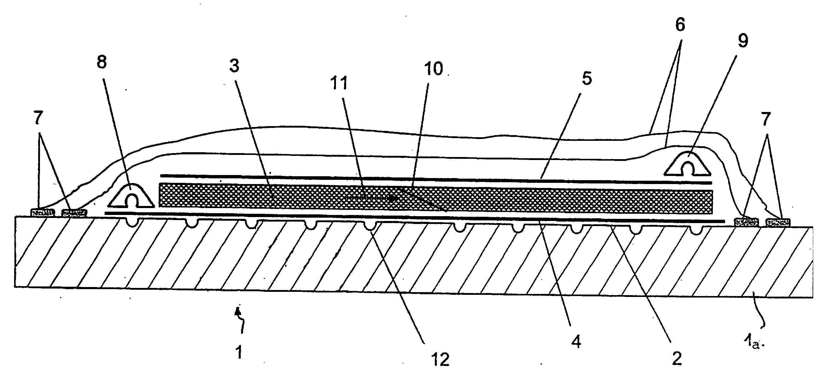
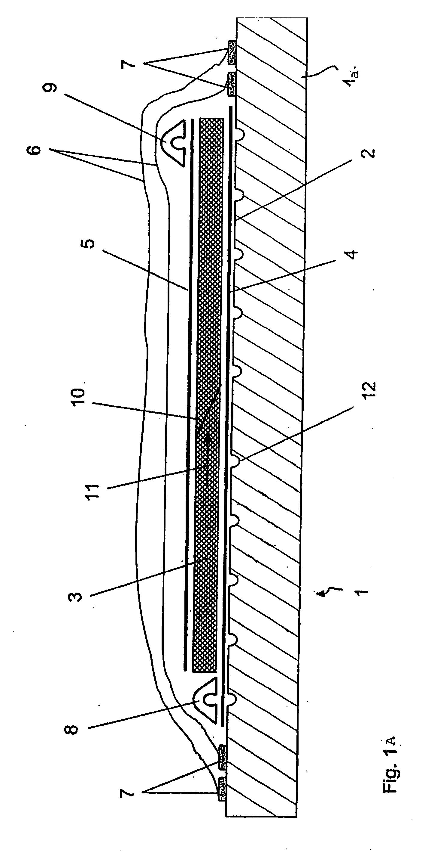
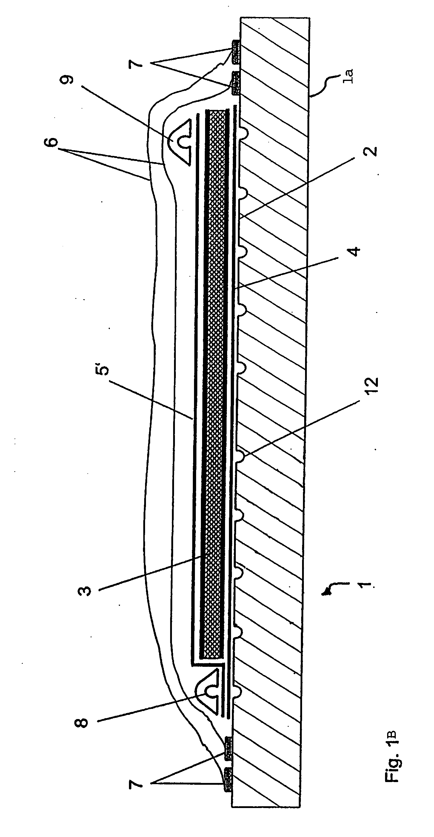
[0036]FIG. 1A shows a view of a section through a tool 1 with a placed-in semifinished fiber product 3 according to an exemplary embodiment of the invention.

[0037]The tool 1 has a table 1a with a surface 2, the form of which defines the form of the components to be produced. The table 1a preferably consists of metal, but may also consist of plastics, ceramics or other suitable materials.

[0038]On the surface 2, the semifinished fiber product 3 is arranged. The semifinished fiber product 3 may be, for example, a laid, woven or knitted fabric, a nonwoven fabric, loose fibers or a sandwich-like structure. The thickness of the semifinished fiber product 3 may also vary over the surface 2.

[0039]A peel ply and / or a release film 4 is / are typically arranged between the surface 2 and the semifinished fiber product 3. In the same way, such a release film and / or peel ply 5 may also be arranged on the semifinished fiber product 3.

[0040]The entire construction is packed in an airtight manner by m...


PUM

PropertyMeasurementUnit
Angleaaaaaaaaaa
Widthaaaaaaaaaa
Widthaaaaaaaaaa

Abstract

The present invention provides a tool for the production of fiber composite components. The tool has a surface for depositing semifinished fiber products on the surface, the surface having a number of openings for feeding a matrix to the deposited semifinished fiber products. It is consequently possible to dispense entirely or partly with a conventional flow promoter and possible to achieve a high quality of fiber composite component.

Description

CROSS-REFERENCE TO RELATED APPLICATIONS[0001]This application claims the benefit of U.S. Provisional Application No. 60 / 838,232, filed Aug. 17, 2006, German Patent Application No. 10 2006 038 665.5 filed on Aug. 17, 2006 and German Patent Application No. 10 2007 013 987.1 filed on Mar. 23, 2007, the complete disclosures of which are herein incorporated by reference.FIELD OF THE INVENTION[0002]The present invention relates to a tool for the production of fiber composite components.BACKGROUND OF THE INVENTION[0003]Although it can be applied to any desired methods for producing fiber composite components, the present invention and the problems on which it is based are explained in more detail with reference to an infusion process.[0004]In the production of a fiber composite component by the infusion process, various auxiliary materials are used, in particular a so-called flow promoter. A flow promoter is typically a knitted fabric with a high permeability. During the production of the ...

Claims


Application Information

Patent Timeline
21 Feb 2008
Publication
US20080044506A1
IPC
B29C70/36
CPC
B29C70/548; B29C70/443
Inventors
ZAHLEN, PIERRE; HEIM, CLEMENS