Safety-enhanced heat tracing

a heat tracer and safety-enhanced technology, applied in the direction of indirect heat exchangers, hose connections, lighting and heating apparatus, etc., can solve the problems of heat tracer burn injuries, work-related burn injuries are a general problem, and present a danger to workers

Inactive Publication Date: 2000-10-17
THERMON INC
View PDF4 Cites 12 Cited by
  • Summary
  • Abstract
  • Description
  • Claims
  • Application Information

AI Technical Summary

Problems solved by technology

A problem with pipes or tubes carrying steam is that they can present a danger to workers who may be required to work on or around them, due to the high pressures and temperatures inherent with steam.
Thus, work-related burn injuries are a problem in general.
Burn injuries from heat tracing is a particular problem, and convection tracing, which is the majority of heat tracing, is the primary source of bums from heat tracing.
However, the desirable goal of reducing burn injuries from heat tracing has been somewhat incompatible with the necessity to maintain process fluids at a desired temperature in an economical fashion.

Method used


Image

  • Safety-enhanced heat tracing
  • Safety-enhanced heat tracing

Examples


Embodiment Construction

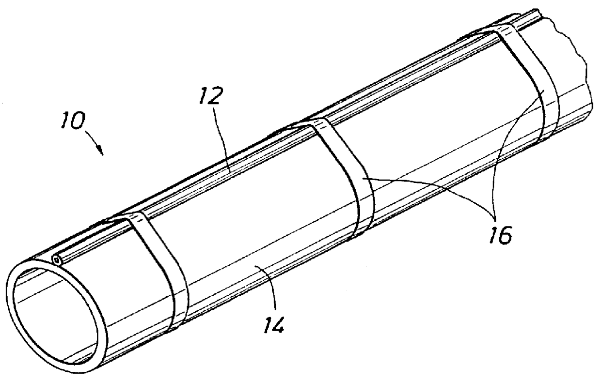
With reference to FIG. 1, a typical prior art heated system 10 includes a bare convection tracer 12 mounted on a process pipe 14. Bare convection tracer 12 is typically a small diameter metallic tube or pipe containing a hot heat-transfer fluid, such as steam. Bare convection tracer 12 is secured to process pipe 14 with a high-temperature tape or banding material 16. Process pipe 14 conveys a process fluid (not shown), which is maintained within a desired temperature range by transfer of heat from tracer 12 through process pipe 14 into the process fluid.

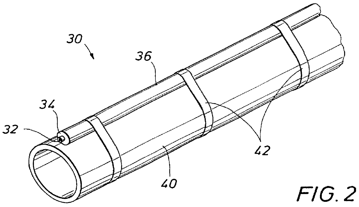
FIG. 2 illustrates a heated system 30 according to the present invention, which includes a heat-convection tracer 32. Tracer 32 is a small diameter tube or pipe and is preferably, but not necessarily, metallic. Tracer tube 32 is externally covered or coated with a thin layer of a polymeric material 34. Polymeric material 34 is typically, but not necessarily, applied to a thickness ranging between approximately 10 mils and 100 mils, p...


PUM


Abstract

Safety-enhanced steam tracing includes a metallic tube with a thin jacket of polymeric material, such as silicone rubber. The polymeric jacket is typically about 40 mils to about 60 mils thick. The safety-enhanced steam tracing provides a substantially lower risk of burn injury than bare metal steam tracing, yet its conductance performance is about the same as that of bare metal steam tracing.

Description

Not applicable.1. Field of the InventionThe present invention relates generally to heat transfer equipment, and more particularly to a heat-tracing apparatus.2. Description of the Related ArtTo ensure the continuity of plant operations in industries, such as refining, chemical, and pulp and paper, process and utility pipes and vessels are often heated by convection steam tracers to keep the contents of fluids such as liquids, gases, vapors, suspensions and slurries from freezing, condensing, crystallizing, separating or becoming too viscous to pump.A standard measurement of steam tracing performance used in industry is conductance. Tracer conductance is designated C.sub.T. The C.sub.T value is derived to reflect the normalized heat transfer coefficient of the heat transfer element (tracer). The coefficient is normalized in terms of a "per unit length," generally reduced to feet. The resulting C.sub.T is commonly given units of BTU / hr-ft-.degree. F.If Q=U.multidot.A.multidot..DELTA.T...

Claims


Application Information

Patent Timeline
Patent Type & Authority Patents(United States)
IPC IPC(8): F16L59/00F16L59/14F16L3/237F16L9/14F16L35/00
CPCF16L3/237F16L59/143F16L35/00
Inventor PITZER, R. KNOXSCHLAMEUS, DAVID L.BARTH, ROY E.
Owner THERMON INC
Why Eureka
Try Eureka