System, apparatus, and method for installing control lines in a well

a technology of control line and system, applied in the direction of drilling pipes, wellbore/well accessories, sealing/packing, etc., can solve the problems of control line crushing or bursting, thin-walled tubes that can easily be damaged, and not necessarily the best arrangemen

Inactive Publication Date: 2000-10-17
TESCO HLDG I
View PDF5 Cites 97 Cited by
  • Summary
  • Abstract
  • Description
  • Claims
  • Application Information

AI Technical Summary

Benefits of technology

Yet another object of thc present invention is to provide a method and apparatus for reducing the time and effort required to secure control lines to a string of well pipe being run into a well.
An important object of the present invention is to provide a method, system, and apparatus for allowing one or more control lines to be secured to a pipe string by a clamp that is attached to the pipe below the device supporting the well string from the drilling ring floor.

Problems solved by technology

The lines, or conduits, referred to herein generically as "control lines," are relatively small diameter, continuous, thin-walled tubes that can easily be damaged during their installation into the well.
If the control line becomes trapped radially between the slips and the pipe, or circumferentially between the slip segments, the control line will be crushed or ruptured.
Such an arrangement may not necessarily be the best arrangement for the well design.
The clamping mechanisms required to secure multiple control lines to the pipe may also interfere with the operation of the spider slips.
The requirement for multiple control lines to extend through the spider also increases the danger of damage to the lines and renders the process more time-consuming and difficult.

Method used


Image

  • System, apparatus, and method for installing control lines in a well
  • System, apparatus, and method for installing control lines in a well
  • System, apparatus, and method for installing control lines in a well

Examples


Embodiment Construction

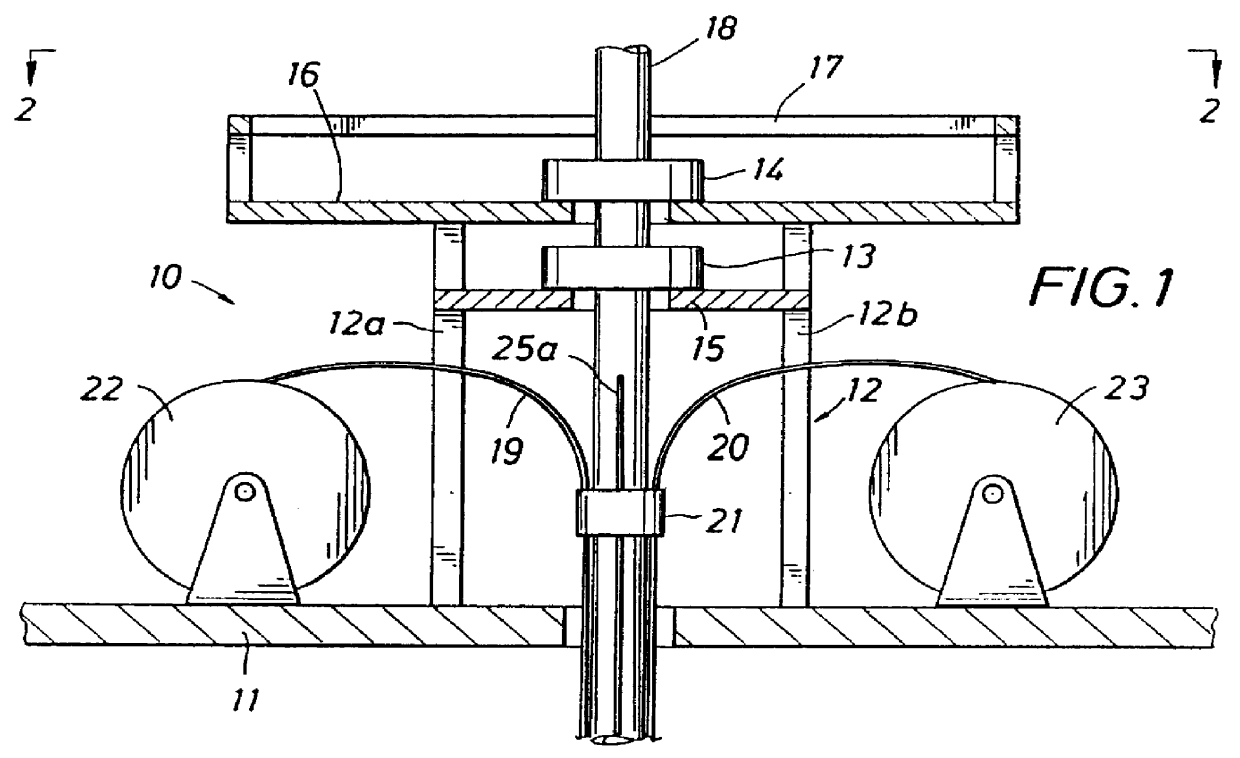
The apparatus of the present invention is indicated generally at 10 in FIG. 1. A rig floor 11 supports a window platform 12 that in turn supports the spiders 13 and 14. The spider 13 is supported on a subfloor 15, and the spider 14 is supported on a work floor 16. Both spiders may be supported on the subfloor 15, or only a single spider may be employed to run the pipe string. A workman's guardrail 17 extends around the perimeter of the work floor 16.

A well pipe 18 extends through the spiders 14 and 13, through the rig floor 11, and into the well (not illustrated). Control lines 19 and 20 are illustrated attached to the pipe 18 with a clamp 21. The control line 19 extends laterally from a supply reel 22, and the control line 20 extends laterally from a supply reel 23.

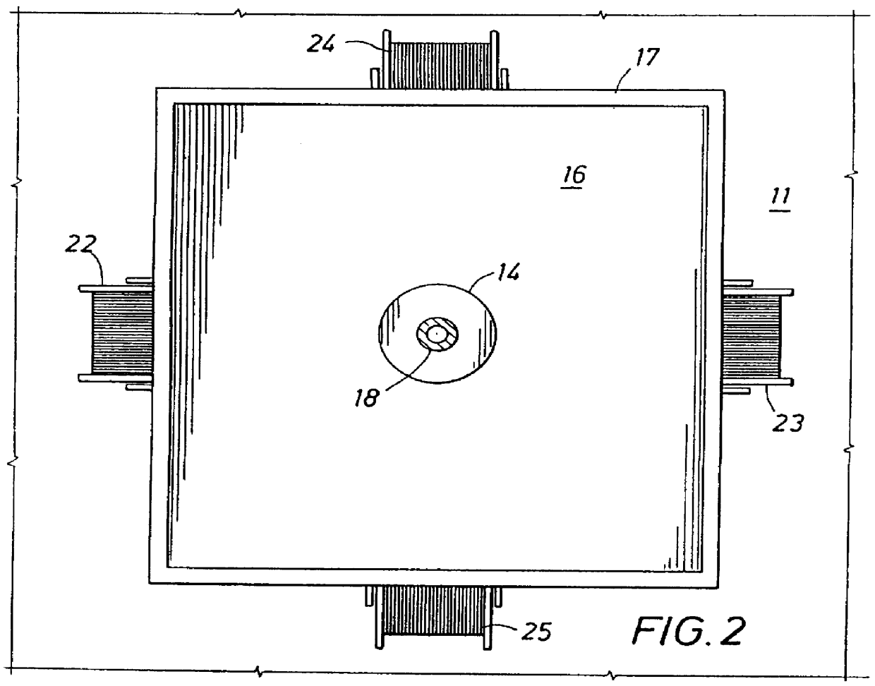
FIG. 2 illustrates an overhead view of the apparatus 10. Two additional conduit supply reels 24 and 25 are illustrated in position to provide control lines to the pipe 18 in a manner similar to that of the reels 22 and 2...


PUM


Abstract

A method and apparatus for installing control lines and pipe into a well. The work surface for equipment and personnel employed in assembling the pipe is elevated above the rig floor. Personnel operating below the work surface use clamps to attach control lines to the pipe being installed in the well. The pipe-holding spiders that arc normally mounted on the rig floor are mounted on the elevated work surface. Assembling the control lines to the pipe below the work surface permits the control lines to be attached to the pipe without first traveling through the spider.

Description

1. Field of the InventionThe present invention relates to methods and means for inserting pipe into a well. More specifically, the present invention relates to systems, methods, and apparatus for attaching conduit used as control lines and injection lines to a string of pipe being inserted into a well.2. Description of the Prior ArtOil and gas wells are sometimes equipped with tubing lines or small diameter conduits that regulate the opening and closing of valves contained within the pipe string or that inject fluids into the well. The lines typically are secured to the outside of the pipe string. The lines used for control can regulate the opening and closing of subsurface valves employed in the production pipe strings in offshore wells to permit the wells to be closed in below the sea bottom. The lines used for injection are frequently employed to add corrosion control or other treating fluids to the fluid being produced from the well. The lines, or conduits, referred to herein ge...

Claims


Application Information

Patent Timeline
Patent Type & Authority Patents(United States)
IPC IPC(8): E21B19/22E21B17/02E21B19/00E21B15/00
CPCE21B15/00E21B17/025E21B19/22E21B19/00E21B17/026
Inventor SONNIER, ERROL A.
Owner TESCO HLDG I
Why Eureka
Try Eureka