Air conditioning apparatus for vehicle with double layer flow mode

Inactive Publication Date: 2000-10-24
DENSO CORP
View PDF15 Cites 39 Cited by
  • Summary
  • Abstract
  • Description
  • Claims
  • Application Information

AI Technical Summary

Problems solved by technology

However, an air conditioning apparatus which can set the double layer flow mode is generally mounted in

Method used


Image

  • Air conditioning apparatus for vehicle with double layer flow mode
  • Air conditioning apparatus for vehicle with double layer flow mode
  • Air conditioning apparatus for vehicle with double layer flow mode

Examples


Embodiment Construction

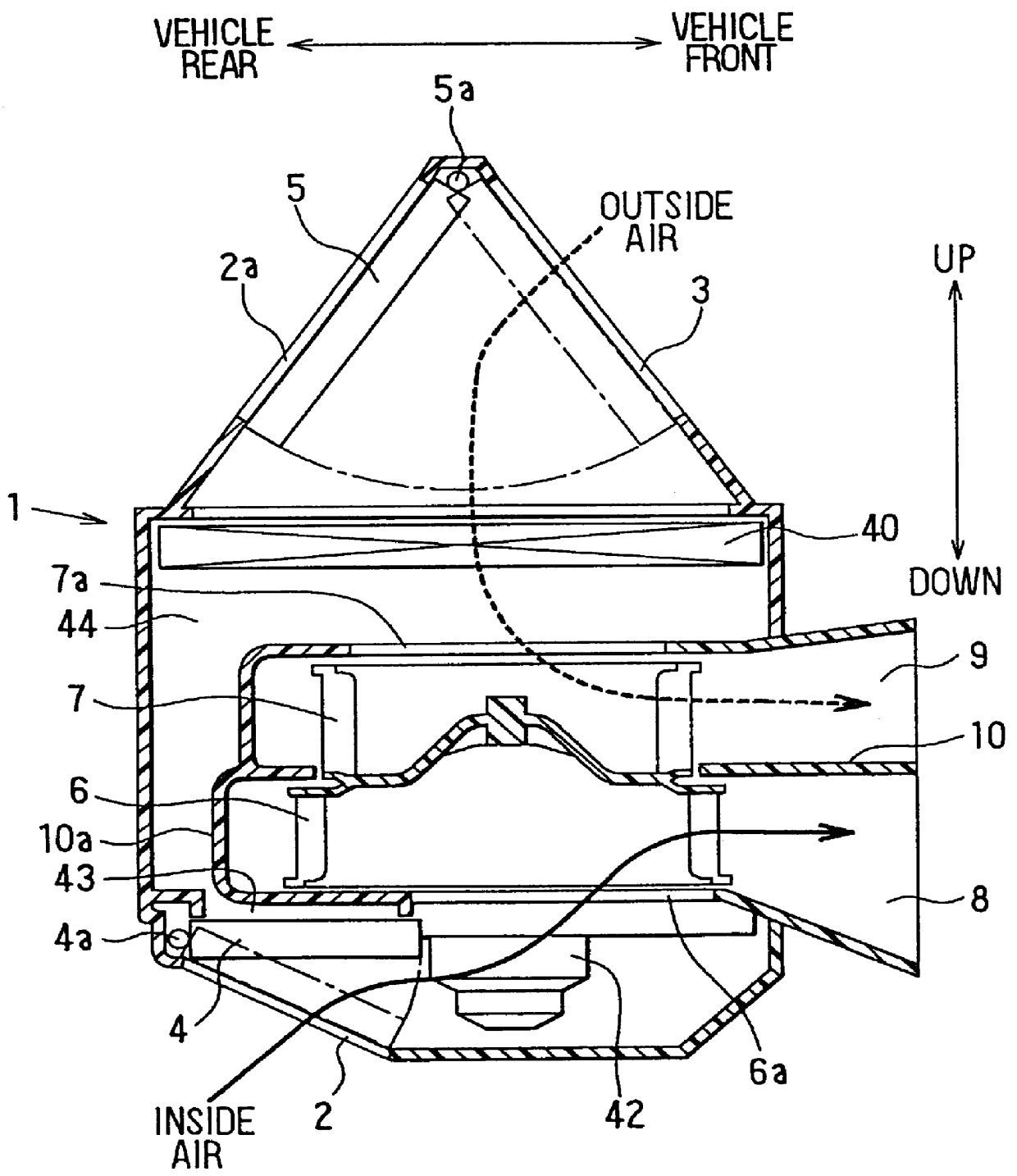
A preferred embodiment of the present invention will be described hereinafter with reference to the accompanying drawings. In the embodiment of the present invention, an air conditioning apparatus is applied to a vehicle having a diesel engine or a lean burn engine, in which heat generated in the engine is too small to heat cooling water with the engine sufficiently.

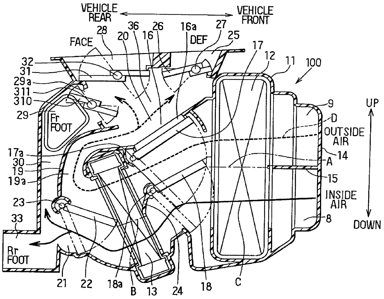
The air conditioning apparatus includes a blower unit 1 shown in FIG. 1, and an air conditioning unit 100 shown in FIG. 2. The air conditioning unit 100 is disposed under an instrument panel in a passenger compartment at an approximate center portion in a left-right direction of the vehicle. On the other hand, the blower unit 1 is disposed under the instrument panel at a side of the air conditioning unit 100 in the left-right direction. In the embodiment, the blower unit 1 is disposed at a front passenger's seat side next to a driver's seat. First, the blower unit 1 will be now described. The blower unit 1 is provided wi...


PUM


Abstract

In an air conditioning apparatus for a vehicle, a double layer flow mode is set when the maximum heating state is set during an air outlet mode where both a foot opening portion and a defroster opening portion are opened. During the double layer flow mode, an air passage of an air conditioning case is partitioned into a first air passage through which inside air flows and a second air passage through which outside air flows, in such a manner that the first air passage communicates with the foot opening portion and the second air passage communicates with the defroster opening portion. When the double layer flow mode is set, the maximum rotation speed of a blower for blowing air is reduced by a predetermined level as compared with an entire outside air mode or an entire inside air mode. Thus, heating capacity for a passenger compartment of the vehicle can be improved.

Description

1. Field of the InventionThis invention relates to an air conditioning apparatus for a vehicle, in which a passage in an air conditioning case is partitioned into a first air passage through which inside air flows and a second air passage through which outside air flows. Inside air having been heated re-circulates and is blown out from a foot air outlet, and outside air having a low-humidity is blown out from a defroster air outlet, to improve both heating capacity for a passenger compartment and defrosting performance for a windshield.2. Description of Related ArtIn a conventional air conditioning apparatus as disclosed in JP-A-5-124426, an inside air introduction port and an outside air introduction port of a blower unit is provided at one end of an air conditioning case, and a foot opening portion, a defroster opening portion and a face opening portion are respectively provided at the other end of the air conditioning case. In the air conditioning case, there is provided a partit...

Claims


Application Information

Patent Timeline
IPC IPC(8): B60H1/00
CPCB60H1/00064B60H2001/00135B60H2001/00107
Inventor NONOYAMA, HIROSHIKAWAI, TAKAYOSHIMURAKI, TOSHIHIKOTAKECHI, TETSUYAYOKOI, JUNJIMIMOTO, MAKOTO
Owner DENSO CORP
Why Eureka
Try Eureka