Nail clipper accessory

a nail clipper and accessory technology, applied in the field of nail clipper accessories, can solve the problems of being unable to handle the clippings,

Inactive Publication Date: 2000-10-31
OWENS SR RANDY J +1
View PDF18 Cites 13 Cited by
  • Summary
  • Abstract
  • Description
  • Claims
  • Application Information

AI Technical Summary

Problems solved by technology

Although nail clipping is necessary many individuals...

Method used


Image

  • Nail clipper accessory
  • Nail clipper accessory
  • Nail clipper accessory

Examples


Embodiment Construction

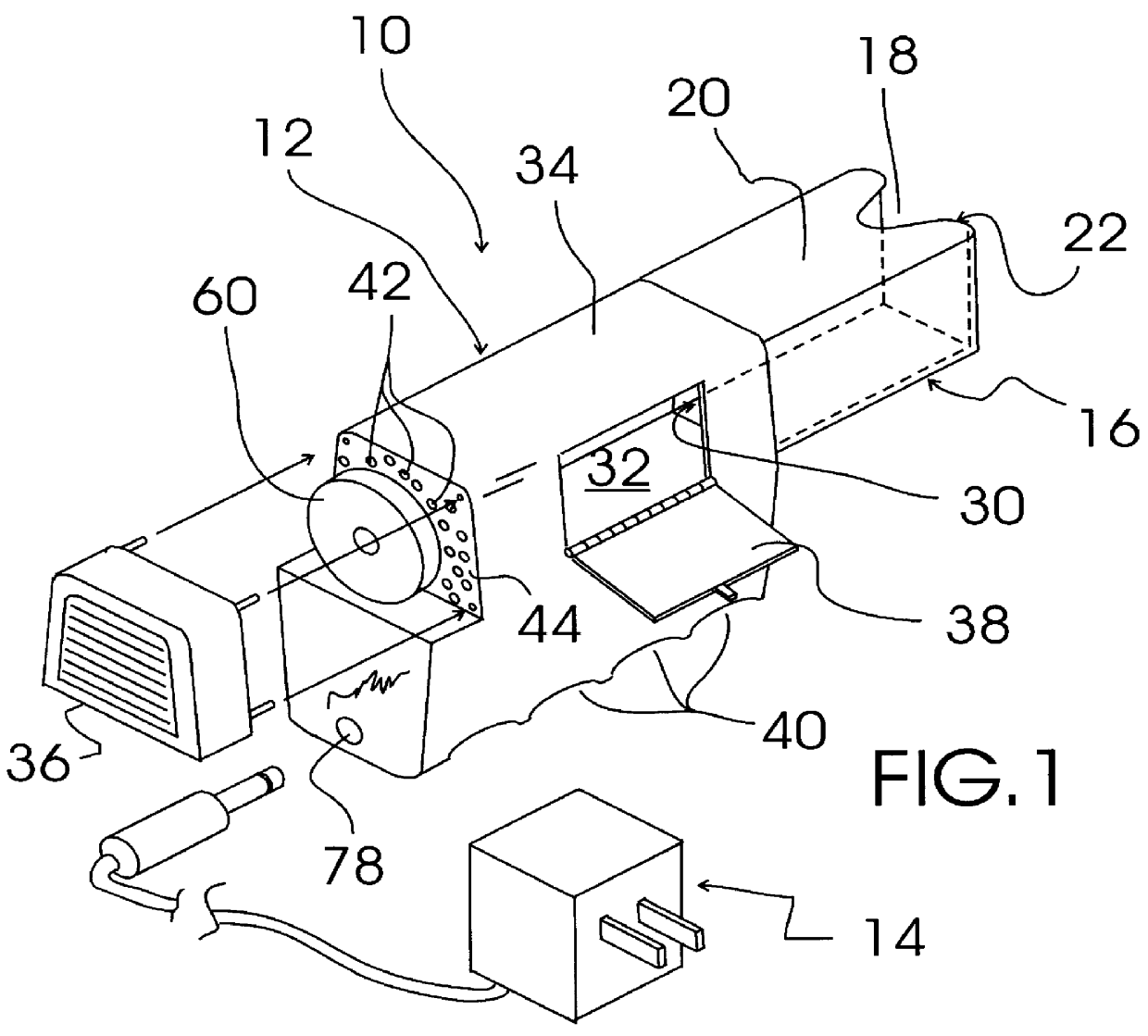
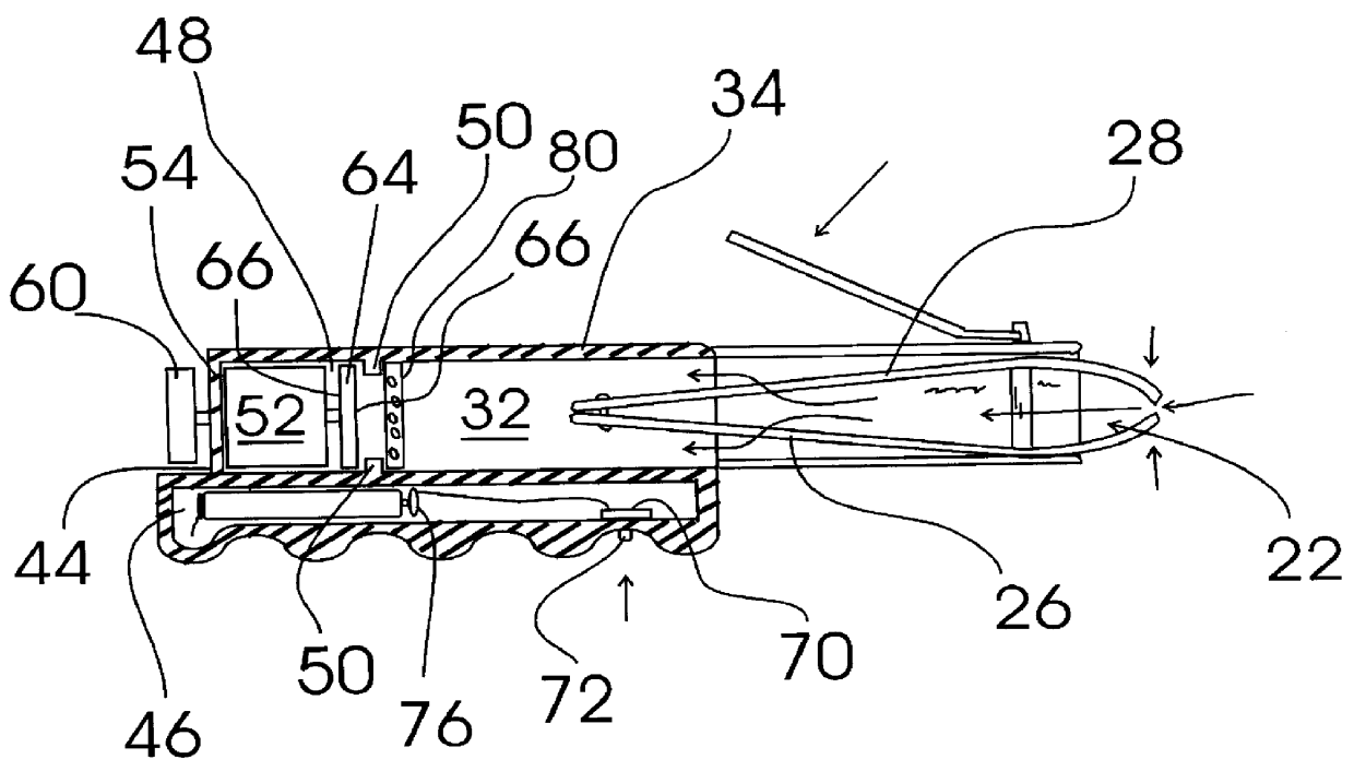
FIG. 1 shows an exemplary embodiment of the nail clipper accessory of the present invention generally designated 10. Nail clipper accessory 10 includes a vacuum assembly, generally designated 12; an AC / DC adapter, generally designated 14; and a resilient tubular clipper shroud structure, generally designated 16. Tubular clipper shroud structure 16 is formed from resilient flexible plastic and has a clipper lever shaft positioning slot 18 formed into a top front surface 20 thereof, an open front end 22 (see also FIG. 2) for receiving a back portion 26 (FIG. 2) of a nail clipper 28 (FIG. 2) and an open rear end 30 in connection with a vacuum chamber 32 of vacuum assembly 12.

Vacuum assembly 12 includes a molded plastic housing 34 including a removable, vented filing stone cover 36, a pivoting vacuum chamber access door 38, a shroud connection opening 30 in corresponding connection with the open rear end 30 of clipper shroud structure 16, a number of finger receiving grooves 40 formed i...


PUM


Abstract

A nail clipper accessory provides a vacuum for collecting the clippings as they are created when using a nail clipper and storing the clippings in a vacuum chamber for later disposal. The accessory is used with convention nail clippers by slipping the rear portion of the nail clipper into a resilient tubular shroud structure. The nail clipper accessory also includes a motor driven filing stone. To reduce the number of motors required for the accessory, the same motor is used to power the vacuum fan and the motor driven filing stone.

Description

The present invention relates to nail clippers and the like and more particularly to a nail clipper accessory that includes a vacuum assembly and a resilient tubular clipper shroud structure; the tubular clipper shroud structure being formed of a resilient flexible plastic and having a clipper lever shaft positioning slot formed into a top front surface thereof, an open front end for receiving a back portion of a nail clipper and an open rear end in connection with a vacuum chamber of the vacuum assembly; the vacuum assembly including a molded plastic housing including a removable, vented filing stone cover, a pivoting vacuum chamber access door, a shroud connection opening in connection with the open rear end of the clipper shroud structure, a number of vacuum fan exhaust openings formed through a back plate surface thereof, a battery chamber formed therein, a DC motor cavity formed therein, a vacuum chamber formed therein and a screen support structure positioned between the vacuu...

Claims


Application Information

Patent Timeline
IPC IPC(8): A45D29/02A45D29/00B26D7/18
CPCB26D7/1863A45D29/023
Inventor OWENS, SR., RANDY J.OWENS, GIDGET T.
Owner OWENS SR RANDY J
Why Eureka
Try Eureka