Boring machine

Inactive Publication Date: 2000-10-31
TRACTO TECHN PAUL SCHMIDT SPEZIALMASCHEN
View PDF12 Cites 4 Cited by
  • Summary
  • Abstract
  • Description
  • Claims
  • Application Information

AI Technical Summary

Benefits of technology

From this starting point, it is an object of the invention to reduce the technical and economic outlay for the production of the liquid pressure

Problems solved by technology

Since borehole lengths of up to 200 m or more occur in

Method used


Image

  • Boring machine
  • Boring machine

Examples


Embodiment Construction

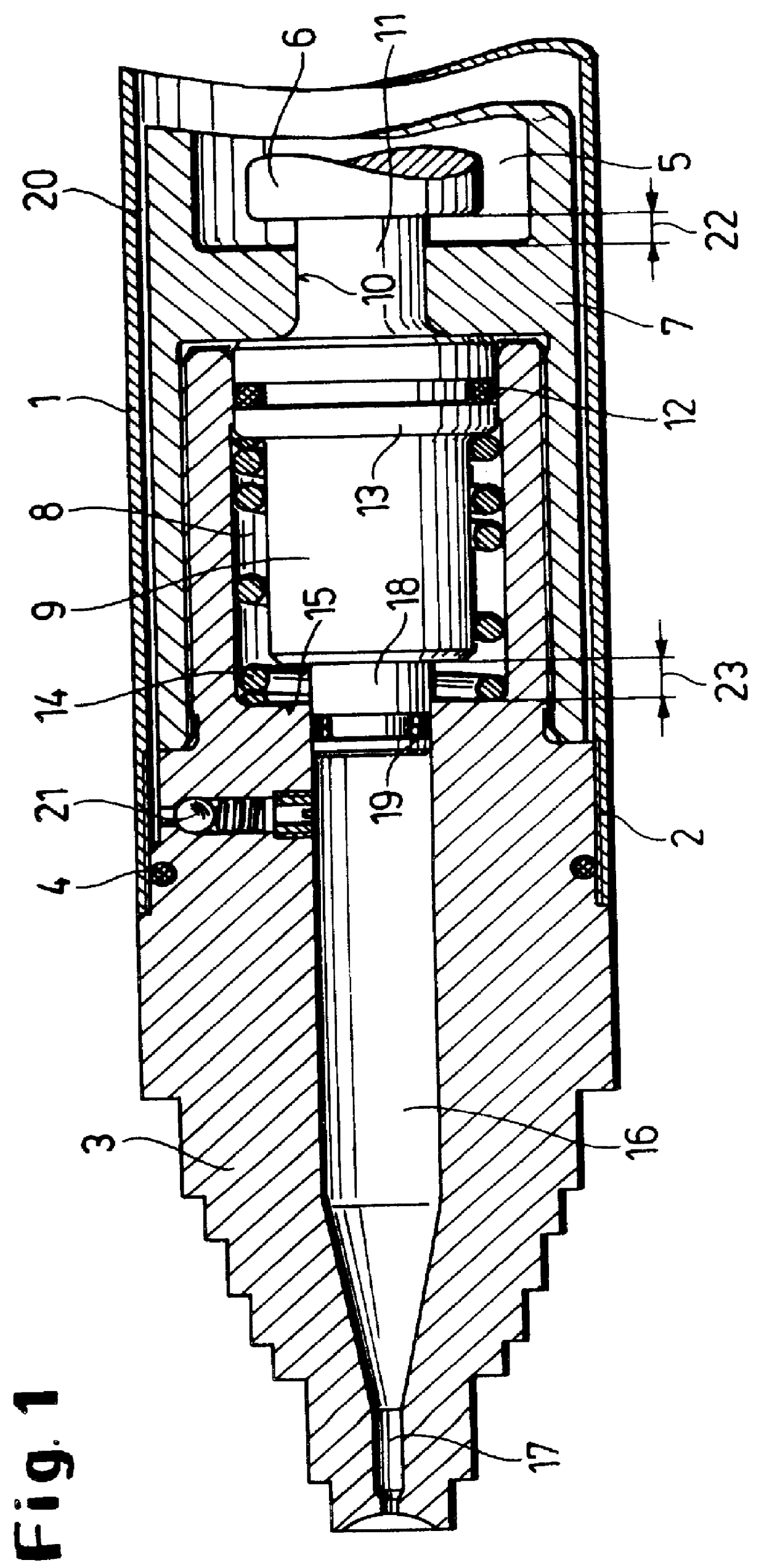
The percussion boring machine comprises a housing 1 which is provided at its forward end with a screw thread 2 into which is screwed a machine tip in the form of a stepped head 3 with a seal 4. In the housing there is a working chamber 5 in which a pneumatically driven automatic striking piston 6 reciprocates. Further details as to this can be found in the above-mentioned patent specification.

The working chamber 5 is separated by an internal collar 7 from a piston chamber 8 located in front of it in the direction of advance and housing a pressure piston 9. At the rear end of the pressure piston 9 there is a spigot 11 which passes through a bore 10 in the internal collar 7 and is in operative connection with the striking piston 6.

The pressure piston 9 is further provided with a sealing ring 12 in contact with the wall of the piston chamber 8, and has a collar 13 by means of which it is supported via a return spring 14 on a shoulder 15 of the striking tip 3. From the piston chamber 8 ...


PUM


Abstract

In a percussion boring machine for producing or widening earth boreholes, the housing is equipped with nozzles and houses a striking piston caused to reciprocate axially by means of compressed air and means of generating pressure which supplies the nozzles with a flushing, cutting, lubricating and/or steering liquid. Since the liquid pressure required for the excavation of the ground surrounding the machine and/or for causing the machine to travel on a curved path is generated in the machine itself, the machine only needs to be supplied through a supply line with a liquid at a slightly raised pressure.

Description

The invention relates to an apparatus and a method, for example for the production or widening of earth boreholes and for laying underground lines without digging a trench or for driving pipes into the ground.BACKGROUND AND PRIOR ARTSuch apparatus, for example percussion boring machines, usually include an automatic striking piston which is caused to reciprocate in the interior of a housing by means of a fluid, for example compressed air, and which imparts its kinetic energy completely to the housing either directly or indirectly through a striking tip which is axially movable in the housing, and possibly also to the ground. In this way the apparatus performs both breaking-up and also displacement and driving work.Boring machines are also known which not only displace the ground but also excavate it and, for example, convey it away counter to the direction of advance.Finally, there are boring machines which permit not only straight-ahead boring but also curved boring. Such machines,...

Claims


Application Information

Patent Timeline
IPC IPC(8): E21B7/18E21B7/00E21B7/26E21B7/20E21B4/14E21B4/00E21B1/12E21B1/26
CPCE21B4/145E21B7/065E21B7/26E21B7/206E21B7/18
Inventor PUTTMANN, FRANZ-JOSEF
Owner TRACTO TECHN PAUL SCHMIDT SPEZIALMASCHEN
Why Eureka
Try Eureka