Positive drive rubber track

a technology of positive drive and rubber track, which is applied in the direction of conveyors, packaging, internal frames, etc., can solve the problems of unavoidable slipping of rubber tracks off sprocket wheels or track rollers of vehicles, and not being met with success

Inactive Publication Date: 2000-10-31
BRIDGESTONE CORP
View PDF8 Cites 42 Cited by
  • Summary
  • Abstract
  • Description
  • Claims
  • Application Information

AI Technical Summary

Problems solved by technology

As a result, the rubber tracks unavoidably get off sprocket wheels or track rollers of the vehicle.
Various attempts have been made in order to prevent the dislodgement of the rubber tracks from the vehicle, but they have not met with success.

Method used


Image

  • Positive drive rubber track
  • Positive drive rubber track
  • Positive drive rubber track

Examples


Embodiment Construction

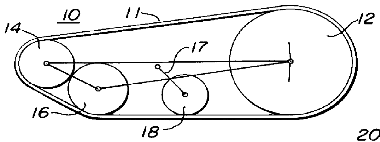
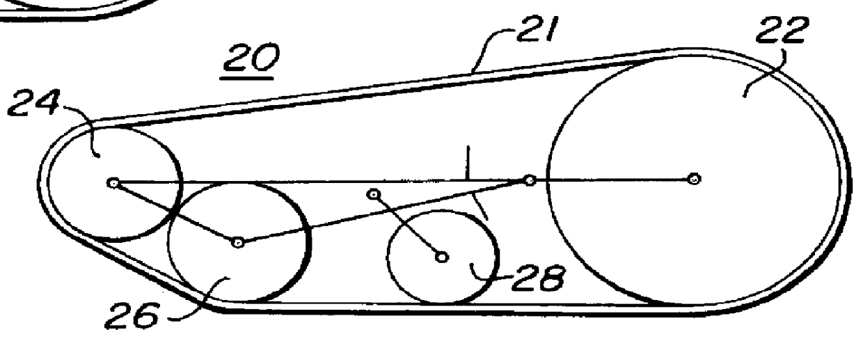
FIG. 1A is a schematic representation of the typical undercarriage of a vehicle that can utilize the positive drive endless rubber track system of the present invention. FIG. 1A illustrates a rigid track frame 10 comprising the sprocket wheel or drive wheel 12, idler wheels 14 and 16, and an adjustable belt tension wheel 18 all of which are encompassed by and in contact with the endless rubber track or drive belt 11. The belt tension wheel 18 may be adjusted as well known with mechanical springs 17 or with hydraulic actuators that are user controlled and may be represented by the numeral 17. Such overall units, as shown, are well known in the art. In like manner, FIG. 1B illustrates a swing-arm-type subcarriage assembly 20 again having a sprocket wheel or drive wheel 22 and idler wheels 24 and 26 and tension adjustment wheel 28 encompassed by and in engagement with an endless rubber track 21 that is driven by wheel 22. The swing-arm track frame of this system is also well known in t...


PUM


Abstract

A positive drive endless rubber track system for the undercarriage of a vehicle, the rubber track including spaced guide lugs projecting inwardly therefrom, the undercarriage including a drive wheel having spaced sprocket pins thereon, idler wheels, and tension adapting wheels around which the endless rubber track is guided and driven by the driving wheel, the drive wheel being attached to the vehicle and having an up-ratio in the range of about 0.5% to about 4.0%.

Description

1. Field of the InventionThe present invention relates in general to endless belt crawler type vehicles and in particular to a positive drive rubber track for such vehicle that has a sprocket up-ratio that provides correct engagement between the sprocket pins on the drive wheel and the regularly spaced guide lugs on the rubber track.2. Description of Related ArtRubber track has become popular due to an increase in construction in urban areas where vehicles having tracks must drive on the pavement and because there is a demand for low soil compaction farming. With the combination of rubber technology and a tremendous amount of trial and error, various types of rubber tracks are now available in the industry. They are used on excavators, dump carriers, boring machines, combines, tractors, and the like. Most of them operate on the job site only and are transported between sites by trucks or trailers. To eliminate the inconvenience of transporting the vehicle between job sites, a vehicl...

Claims


Application Information

Patent Timeline
Patent Type & Authority Patents(United States)
IPC IPC(8): B62D55/24B62D55/12B62D55/30
CPCB62D55/24
Inventor MURAMATSU, TATEO
Owner BRIDGESTONE CORP
Why Eureka
Try Eureka