Angled illumination tube

a technology of illumination tube and angled tube, which is applied in the direction of lighting and heating apparatus, instruments, mechanical equipment, etc., can solve the problems of lowering the efficiency of guiding the light past the reflector and failing to achieve uniform illumination over the entire length of the tub

Inactive Publication Date: 2000-11-21
MATSUSHITA ELECTRIC WORKS LTD
View PDF4 Cites 46 Cited by
  • Summary
  • Abstract
  • Description
  • Claims
  • Application Information

AI Technical Summary

Problems solved by technology

However, the use of the reflector inherently poses a problem of leaving a dark spot behind the reflector at the bend.
In order to reduce the area of the dark spot, the reflector had to be made small which eventually lowers an efficiency of guiding the light past the reflector, failing to achieve uniform illumination over the entire length of the tube.

Method used


Image

  • Angled illumination tube
  • Angled illumination tube
  • Angled illumination tube

Examples


first embodiment

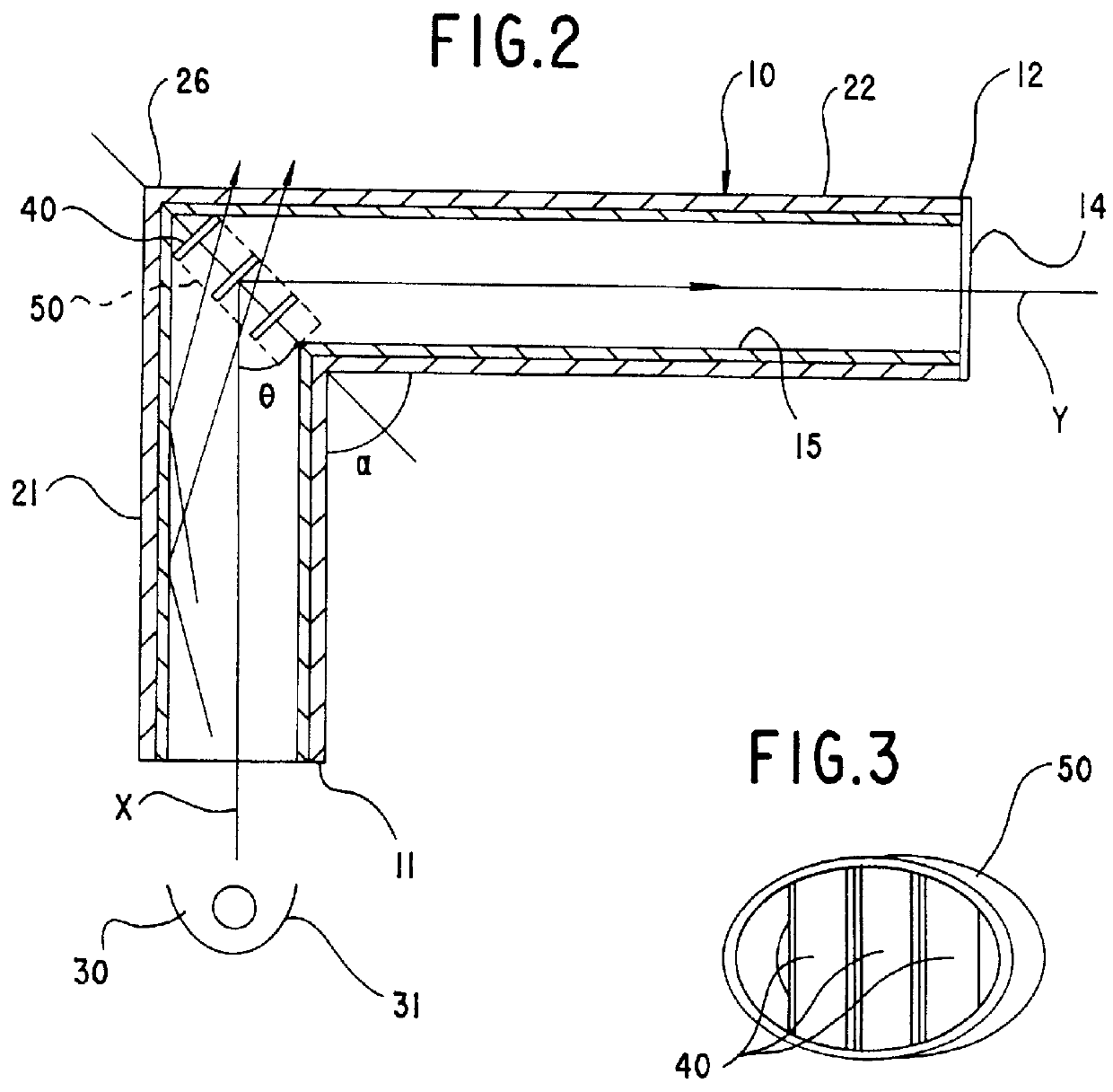
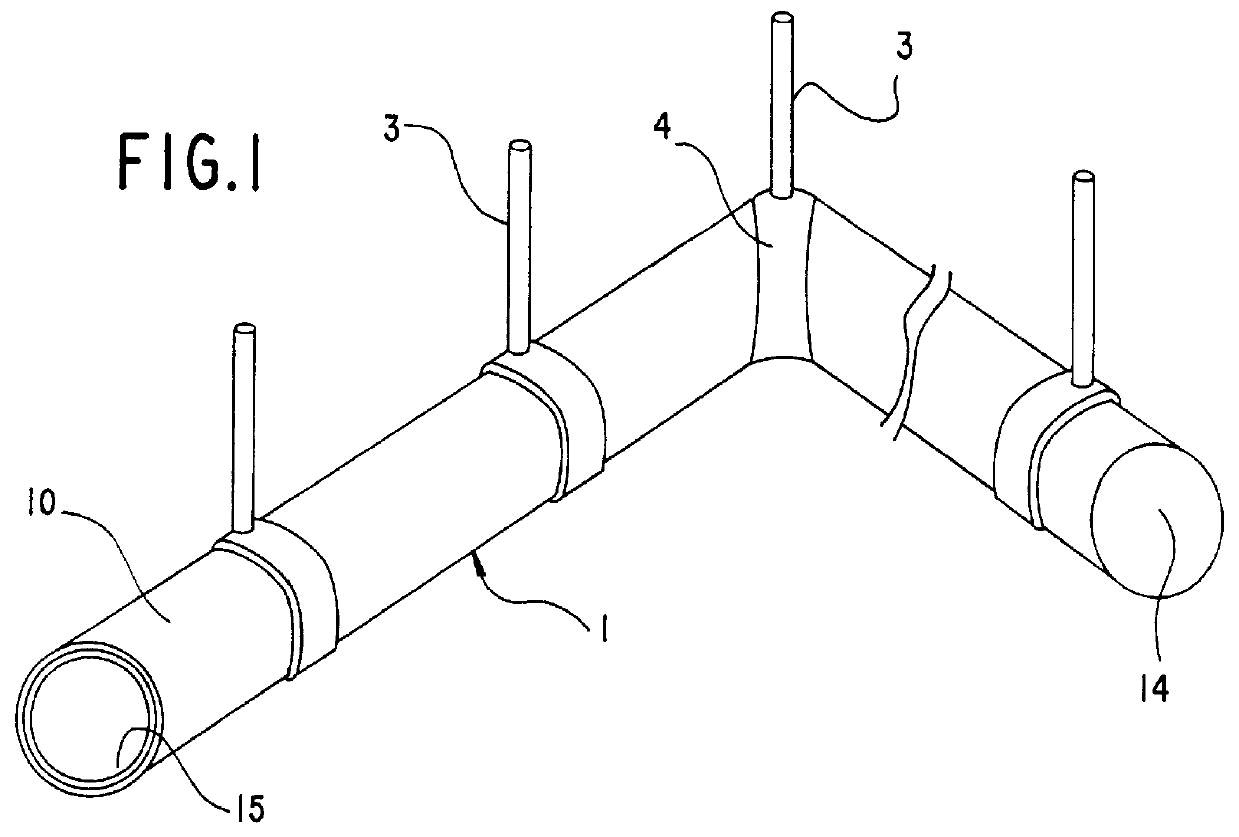
Referring now to FIGS. 1 to 3, there is shown an angled illumination tube 1 in accordance with the present invention. The tube 1 is shown to be suspended from a ceiling by means of hangers 3, and is composed of a transparent L-shaped tubular conduit 10 with a first straight portion 21 and a second straight portion 22 connected at an angle (.alpha.) to the first straight portion 21 to form a bend 26 between first and second ends 11 and 12 on opposite ends of the tube. An external light source 30 with a reflector 31 is provided in proximity to the first end 11 of the first straight portion 21 to emit a light beam into the tube 1. The second end 12 of the second portion 22 is closed by a reflector 14. Alternatively, an additional light source may be provided in proximity to the second end 12 to introduce another light beam into the tube.

The conduit 10 is provided on its interior surface with a light conductive layer 15 in the form of a transparent prismatic film for guiding the light b...

ninth embodiment

FIG. 16 illustrates an angled illumination tube in accordance with the present invention which is similar to the forth embodiment of FIG. 11 except for the addition of a supplementary mirror 46H. The supplementary mirror 46H is provided for each of arrays of mirrors 40H in parallel relation to the mirrors, in order to increase the amount of the reflected light beam towards second straight portions 22H from a first straight portion 21H.

FIG. 17 illustrates an angled illumination tube in accordance with a tenth embodiment of the present invention which is similar to the fifth embodiment of FIG. 12 except for the addition of a supplementary mirror 46J. The supplementary mirror 46J is provided for each of the arrays of mirrors 40J in the same plane of an outermost mirror 40J in each array remote from a first straight portion 21J, thereby increasing the amount of the reflected light beam towards second straight portions 22J.

FIG. 18 illustrates an angled illumination tube in accordance wit...


PUM


Abstract

An angled illumination tube is capable of reducing a dark spot behind the reflector, while illuminating the tube uniformly over the length of the tube. The tube is used in combination with a light source providing a light beam and comprises an angled transparent tubular conduit having a first end and a second end on opposite longitudinal ends of the conduit. The conduit has a bend between the first and second longitudinal ends, and is used with the first end receiving the light beam from the light source in order to guide the light beam along the length of the conduit. A reflector is disposed within the bend to reflect the light beam from the first end to direct a reflected light beam towards the second end. The reflector defines an incident light axis along which the light beam is guided to the reflector, and a reflected light axis along which the reflected light beam is directed to said second end. The reflector is composed of a plurality of mirrors arranged in a parallel array along a bisector that divides an included angle between the incident and reflected light axes at an angle ( theta ) with respect to the incident light axis. Two adjacent ones of the mirrors are spaced at a fixed distance (d) along the bisector and of uniform length (L) measured within a plane including the incident and reflected light axes. The mirrors are arranged to satisfy the following relation:

Description

1. Field of the InventionThe present invention is directed to an angled illumination tube adapted in use for guiding and distributing a light beam for emission of the light over the length of the tube, and more particularly to the illumination tube having a bend intermediate its ends.2. Description of the Prior ArtIllumination tubes are widely utilized in the art as a long lighting system adapted in use to be routed along a wall, ceiling or the like structure of a building for lighting a wide area. U.S. Pat. No. 5,016,143 discloses a typical lighting tube which is L-shaped to have a bend intermediate its lengthwise ends. A light source is located at one lengthwise end of the tube to emit a light beam towards the bend. A single reflector is provided inside of the bend to reflect the light beam to direct a reflected light towards the opposite lengthwise end in order to illuminate the tube over the full length thereof by passing a portion of the light through a transparent wall of the ...

Claims


Application Information

Patent Timeline
Patent Type & Authority Patents(United States)
IPC IPC(8): F21V8/00G02B6/00F21S2/00G02B17/00
CPCG02B17/006G02B6/0096G02B6/0001
Inventor KURAMITSU, OSAMUMURAKAMI, TADASHISAKAMOTO, KEIJIYAMADA, MAKOTO
Owner MATSUSHITA ELECTRIC WORKS LTD
Why Eureka
Try Eureka