Pressure pulsations reducing compressor

a compressor and pressure pulsation technology, applied in the field of compressors, can solve the problems of high-pressure discharge gas upstream of the check valve, external refrigerant circuit to generate vibration and acoustic noise, and flow back into the check valv

Inactive Publication Date: 2000-11-21
TOYOTA IND CORP
View PDF17 Cites 43 Cited by
  • Summary
  • Abstract
  • Description
  • Claims
  • Application Information

AI Technical Summary

Problems solved by technology

Discharge gas pressure pulsations are damped in the discharge muffler by causing reflection and interference in its muffling space.
A conventional compressor employing the aforementioned arrangement, however, would still produce discharge gas pressure pulsations when a valve element of its check valve begins to hunt, and such pressure pulsations are likely to cause the external refrigerant circuit to generate vibrations and acoustic noise.
Another problem of the conventional arrangement in which the check valve is provided downstream of the discharge muffler is that the high-pressure discharge gas upstream of the check valve as well as the volumetric capacity of the discharge muffler flows back into a crankcase of the compressor when the compressor is not in operation.
This results in an excessive increase in the internal pressure of the crankcase and produces an adverse effect on the durability of a lip-type seal mounted on a rotary shaft of the compressor.
If the capacity control valve is opened when the compressor has been stopped in this construction, the refrigerant gas in the discharge chamber is supplied to the crankcase through the pressure supply channel, causing an increase in the internal pressure of the crankcase.

Method used


Image

  • Pressure pulsations reducing compressor
  • Pressure pulsations reducing compressor
  • Pressure pulsations reducing compressor

Examples


Embodiment Construction

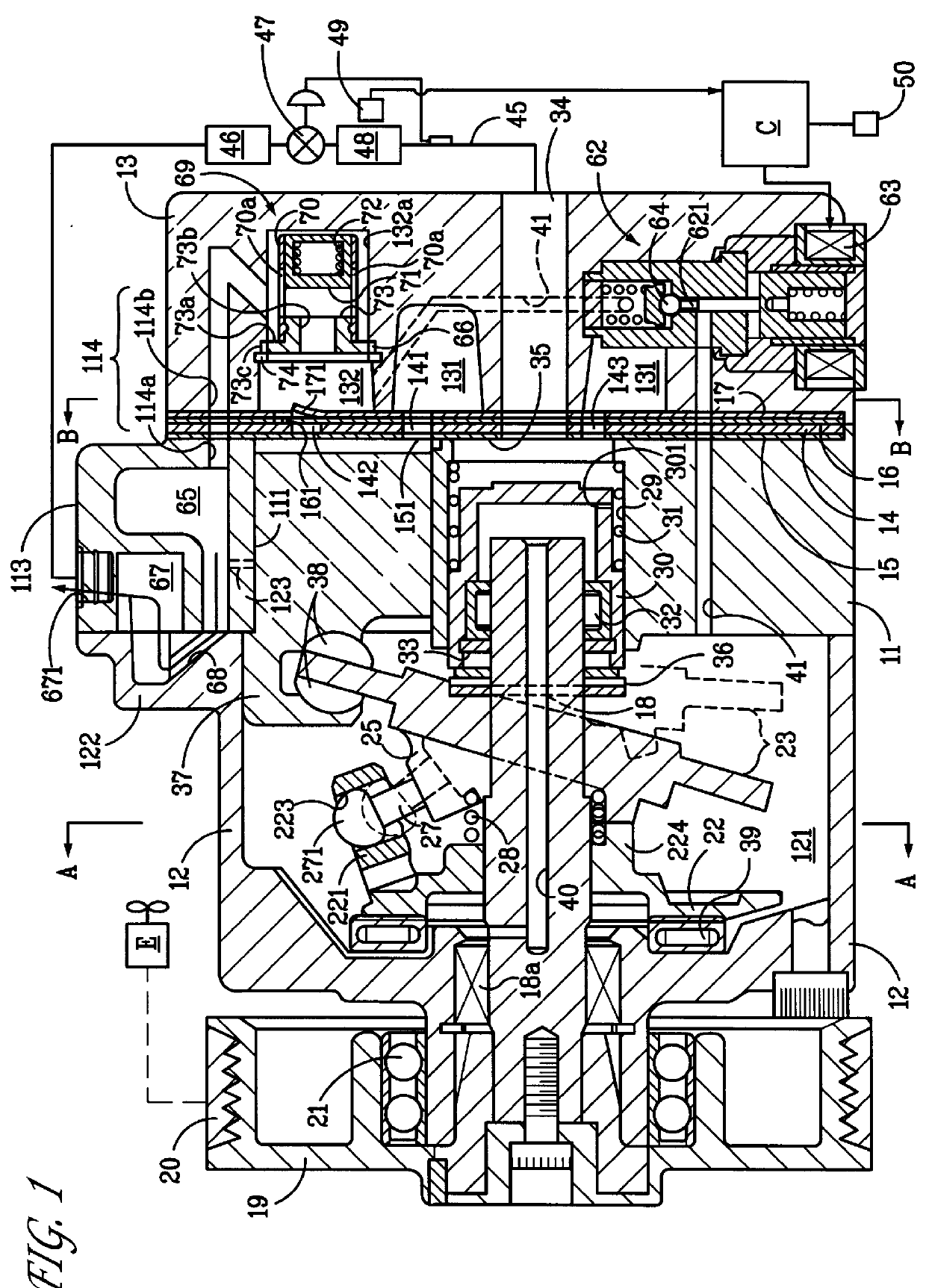
The invention is now described in detail, by way of example, with reference to its currently preferred embodiment in a clutchless variable displacement compressor, as depicted in FIGS. 1 to 6.

As shown in FIG. 1, a front housing block 12 is joined to a front end of a cylinder block 11, and a rear housing block 13 is firmly joined to the a rear end of the cylinder block 11 with a valve plate 14, valve-forming plates 15, 16 and a retainer-forming plate 17 placed in between. The front housing block 12, the cylinder block 11, and the rear housing block 13 thus assembled together form a housing of the compressor. A rotary shaft 18 is rotatably supported between the front housing block 12, in which a crankcase 121 is formed, and the cylinder block 11. A front end portion of the rotary shaft 18 protrudes outward from the crankcase 121 and a pulley 19 is firmly mounted on the front end portion of the rotary shaft 18. The pulley 19 is connected to a vehicle engine E by a belt 20 and is suppor...


PUM


Abstract

In a variable displacement compressor of the invention, cylinder bores (111) and a crankcase (121) are formed in a housing, single-ended pistons (37) are fitted in the cylinder bores (111), and a cam plate (23) is provided in the crankcase (121). The displacement capacity of the compressor is varied by controlling the angle of inclination of the cam plate (23) in accordance with the difference between the internal pressure of the crankcase (121) and an suction pressure present on both sides of each single-ended piston (37). A dampening or muffler chamber (65) is provided downstream of an output channel (114) through which a refrigerant gas discharged from the cylinder bores (111) passes. A check valve (69) which opens and closes in accordance with a pressure difference between upstream and downstream sides of the output channel (114) is provided in the output channel (114), upstream of the muffler chamber (65). The present invention reduces the effects of pressure pulsations caused by the compression motion of the compressor and caused by the valve body of the open/close device hunting, has no bad effects on the external refrigerant circuit connected to the compressor, and increases the reliability of the lip seal.

Description

BACKGROUND OF THE INVENTION AND RELATED ART STATEMENT1. Field of the InventionThe present invention pertains generally to compressors and, more particularly, relates to compressors provided with a discharge muffler in a discharge passage.2. Description of the Related ArtIt is known that some conventional compressors, including variable displacement compressors, are provided with an expansion-type discharge muffler in a discharge passage for reducing vibrations and acoustic noise generated when the compressors are in operation. The cross-sectional area of a discharge gas passage is enlarged and then reduced in a muffling space formed in the discharge muffler. Discharge gas pressure pulsations are damped in the discharge muffler by causing reflection and interference in its muffling space. Since the discharge gas pressure pulsations are damped in this manner, it is possible to prevent vibrations and acoustic noise which could occur in an external refrigerant circuit due to the pressur...

Claims


Application Information

Patent Timeline
Patent Type & Authority Patents(United States)
IPC IPC(8): F04B49/22F04B39/00F04B27/10F04B27/08
CPCF04B27/1036F04B49/225F04B39/0055F04B27/08
Inventor MIZUTANI, HIDEKIKAYUKAWA, HIROAKIKANZAKI, SHIGEKIYAMADA, KIYOHIRO
Owner TOYOTA IND CORP
Why Eureka
Try Eureka