DC-DC converter

Inactive Publication Date: 2000-11-28
RICOH ELECTRONIC DEVICES CO LTD
View PDF4 Cites 95 Cited by
  • Summary
  • Abstract
  • Description
  • Claims
  • Application Information

AI Technical Summary

Problems solved by technology

However, in this DC-DC converter 2A in the prior art, because switching is performed such that the pulse-width modulation control or the pulse-frequency modulation control is used according to the load condition, although the efficien

Method used


Image

  • DC-DC converter
  • DC-DC converter
  • DC-DC converter

Examples


Example

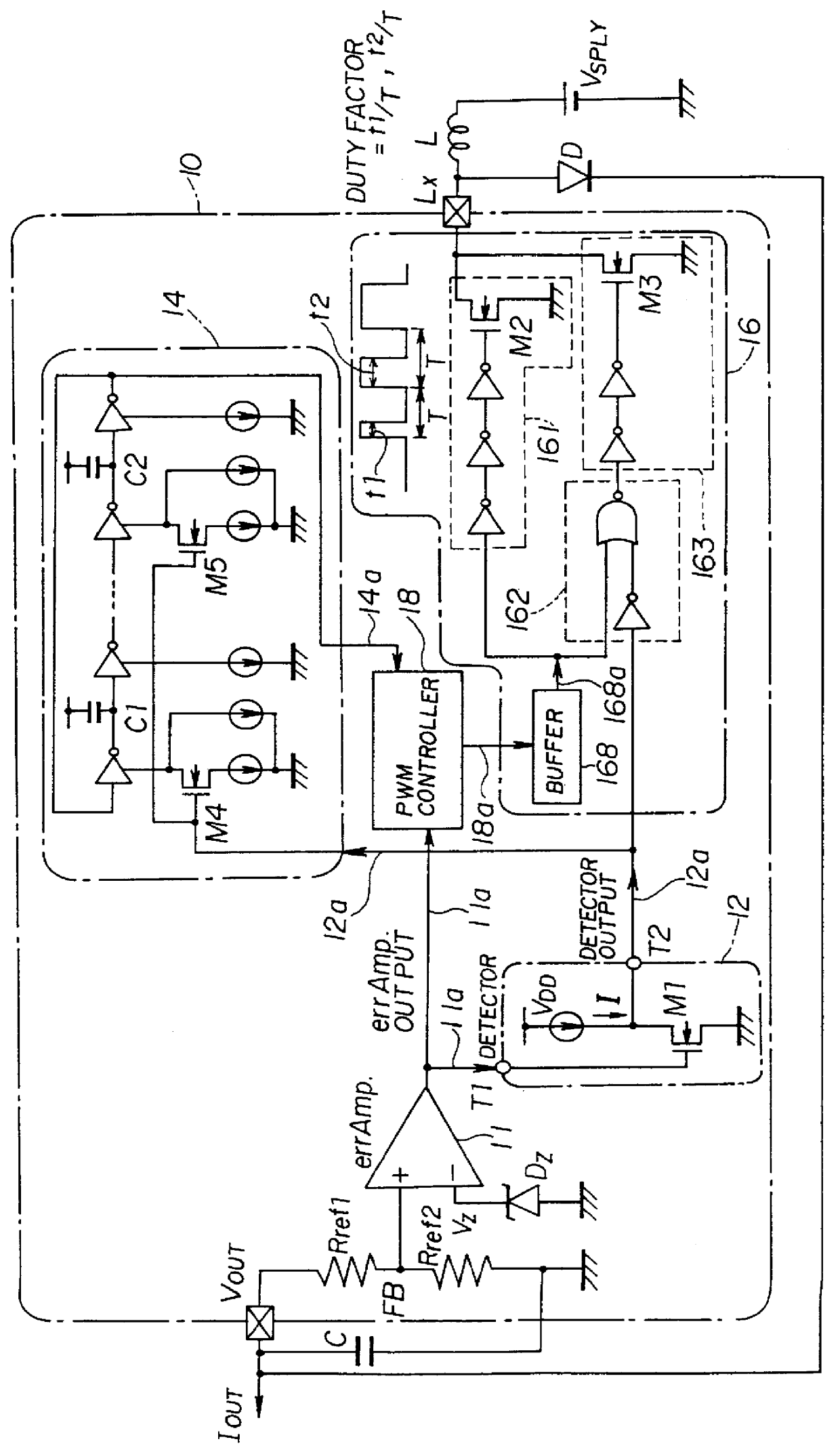
FIG. 2 shows a functional block diagram of a DC-DC converter 10 in a first embodiment of the present invention.

The DC-DC converter 10 is a kind of a switching-type constant-voltage power supply (voltage regulator) in which switching control is performed on switching transistors M2 and M3 so that an external provision voltage V.sub.SPLY, which is provided to a power-source connection terminal Lx via a constant-voltage generating inductor L from an external supply power source such as a lithium battery or the like, is converted into an output direct-current voltage V.sub.OUT of a constant voltage (having undergone voltage regulation) using a constant-voltage generating arrangement which includes the constant-voltage generating inductor L, a constant-voltage generating capacitor C and a rectifying diode D. This DC-DC converter can perform a pulse-width modulation (PWM) control in which a duty factor which is a ratio of the ON period (conduction period) to the total of the ON period and...

Example

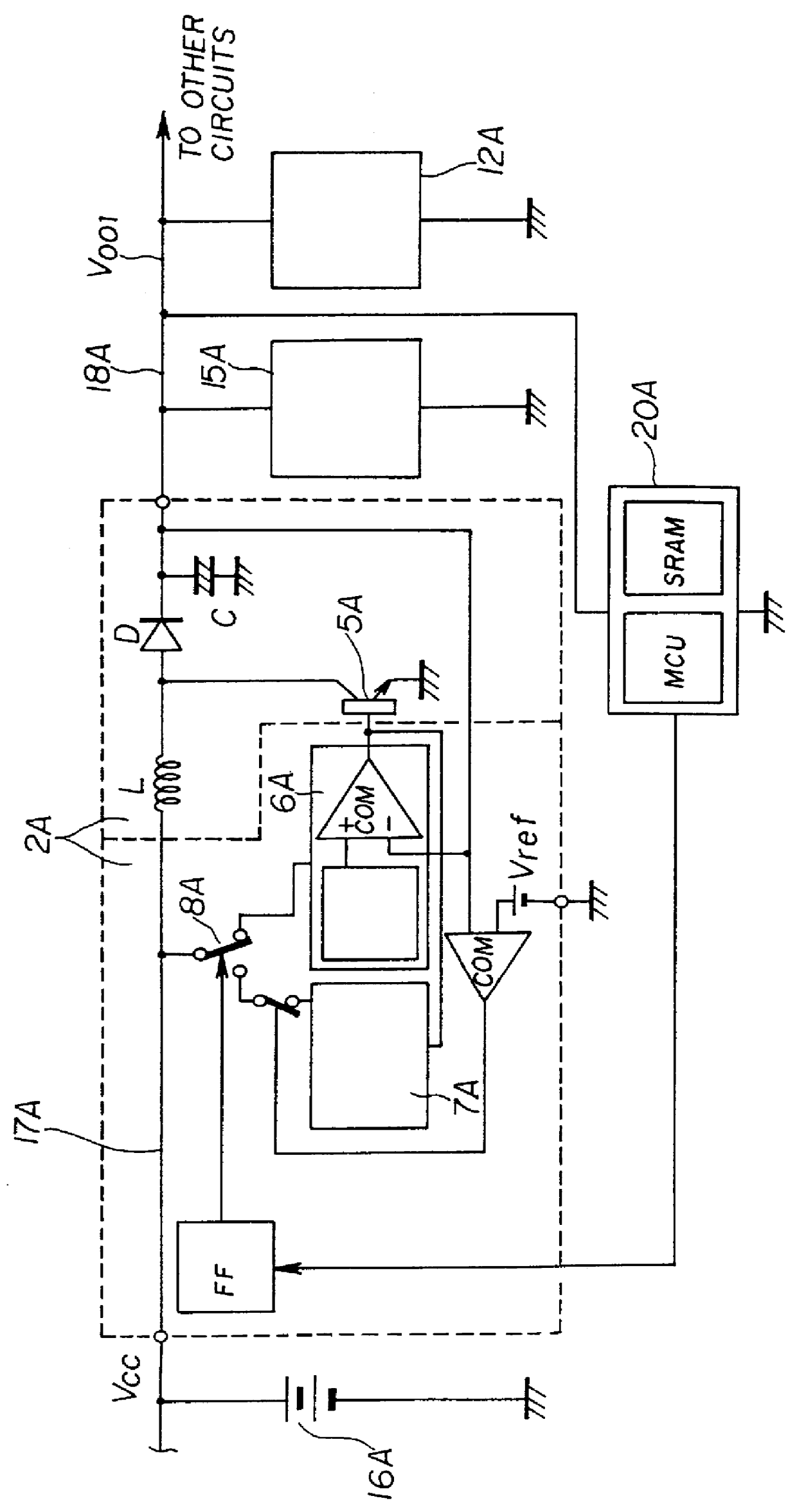
FIG. 5 shows a functional block diagram of a DC-DC converter 10B in a second embodiment of the present invention. The same reference numerals are given to portions / components the same as those shown in FIG. 2. The same reference numeral with `B` added thereto is given to a portion corresponding to that shown in FIG. 2.

The difference between the DC-DC converter 10 shown in FIG. 2 and the DC-DC converter 10B shown in FIG. 5 is that the switching transistors M4 and M5 of the PWM-control-frequency generating oscillator 14 are omitted in the DC-DC converter 10B shown in FIG. 5. Therefore, the PWM control frequency f of the PWM-control-frequency generating oscillator 14 is not changed.

In the DC-DC converter 10B shown in FIG. 5, the pulse-width modulation (PWM) control is performed as follows: When the output current (load current) I.sub.OUT increases, the signal level of the errAmp output 11a is shifted to a lower electric potential so as to increase the above-mentioned duty factor, as sh...

Example

FIG. 6 shows a functional block diagram of a DC-DC converter 10C in a third embodiment of the present invention. The same reference numerals are given to portions / components the same as those shown in FIG. 2. The same reference numeral with `C` added thereto is given to a portion corresponding to that shown in FIG. 2.

The difference between the DC-DC converter 10 shown in FIG. 2 and the DC-DC converter 10C shown in FIG. 6 is that the driver selecting portion 162 and the second driver 163 of the gate-size changing portion 16 are omitted in the DC-DC converter 10C shown in FIG. 6. Therefore, the total gate size of the switching transistor (M2) in the gate changing portion is not changed.

In the DC-DC converter 10B shown in FIG. 6, the pulse-width modulation control is performed as follows: When the PWM-control-frequency generating oscillator 14 determines based on the load-light / heavy detection signal 12a that the load-side output direct current I.sub.OUT has decreased, that is, when th...


PUM


Abstract

A controller generates a load control signal for pulse-width modulation control for changing the duty factor of switching transistors so that the ON period of the switching transistors is elongated when said controller determines based on an error detection amplification signal that the load-side output direct current has increased, and the ON period of the switching transistors is shortened when said controller determines based on the error detection amplification signal that the load-side output direct current has decreased, in the condition in which the switching frequency is kept constant. A driver selecting portion selects, according to the load-light/heavy detection signal, at least one switching transistor to be activated, from among the plurality of switching transistors, and supplying the load control signal to the thus-selected at least one switching transistor.

Description

1. Field of the InventionThe present invention relates to a semiconductor device for power supply, and, in particular, to a DC-DC converter which is a kind of a switching-type constant-voltage power supply in which, when an externally supplied voltage given by an external supply power source such as a battery or the like is converted into a predetermined constant voltage, and, then, is outputted, determination is made as to whether a condition of a load to which the constant voltage is provided is a heavy load condition or a light load condition, and switching of a switching transistor is controlled in accordance with the load condition so that an improvement in power-supply efficiency is achieved at the time of a light load.2. Description of the Prior ArtAs such a kind of DC-DC converter in the prior art, there is one which is disclosed in Japanese Laid-Open Patent Application No. 7-322608 (see FIG. 1), for example.Specifically, a DC-DC converter 2A in the prior art, shown in FIG. ...

Claims


Application Information

Patent Timeline
IPC IPC(8): H02M3/158H02M3/04
CPCH02M3/158Y02B70/16H02M2001/0032H02M1/0032Y02B70/10
Inventor ICHIBA, KOHJI
Owner RICOH ELECTRONIC DEVICES CO LTD
Why Eureka
Try Eureka