Methods and apparatus for detecting and locating cable failure in communication systems

a communication system and cable failure technology, applied in the field of methods and apparatus for cable failure detection in communication systems, can solve problems such as failure of cable connected between remote terminals, network switching failure, and inability to detect and locate methods and apparatuses in the prior ar

Inactive Publication Date: 2000-11-28
AMERICAN TELEPHONE & TELEGRAPH CO
View PDF13 Cites 38 Cited by
  • Summary
  • Abstract
  • Description
  • Claims
  • Application Information

AI Technical Summary

Problems solved by technology

In many instances, a network switching failure can be attributed to a bad or disconnected T3 cable interconnecting remote switching centers.
One problem with such a failure is detecting and identifying the cable end at which the failure has occurred.
Another problem is determining the access provider responsible for the failed cable and restoring service to the switching center.
None of the prior art discloses methods and apparatus for detecting and locating which end of a cable connected between remote terminals has failed and the identity of the service provider of the failed cable.
If the data signal Ds detected by the signal generator and monitor is degraded from the reference signal Rs, a cable failure has occurred in the switching center at the far or remote end of the cable connected to the port.
If the data signal Ds detected by the signal generator and monitor matches the reference signal Rs, a cable failure has occurred at the near end or at the cable port in the switching center.

Method used


Image

  • Methods and apparatus for detecting and locating cable failure in communication systems
  • Methods and apparatus for detecting and locating cable failure in communication systems
  • Methods and apparatus for detecting and locating cable failure in communication systems

Examples


Embodiment Construction

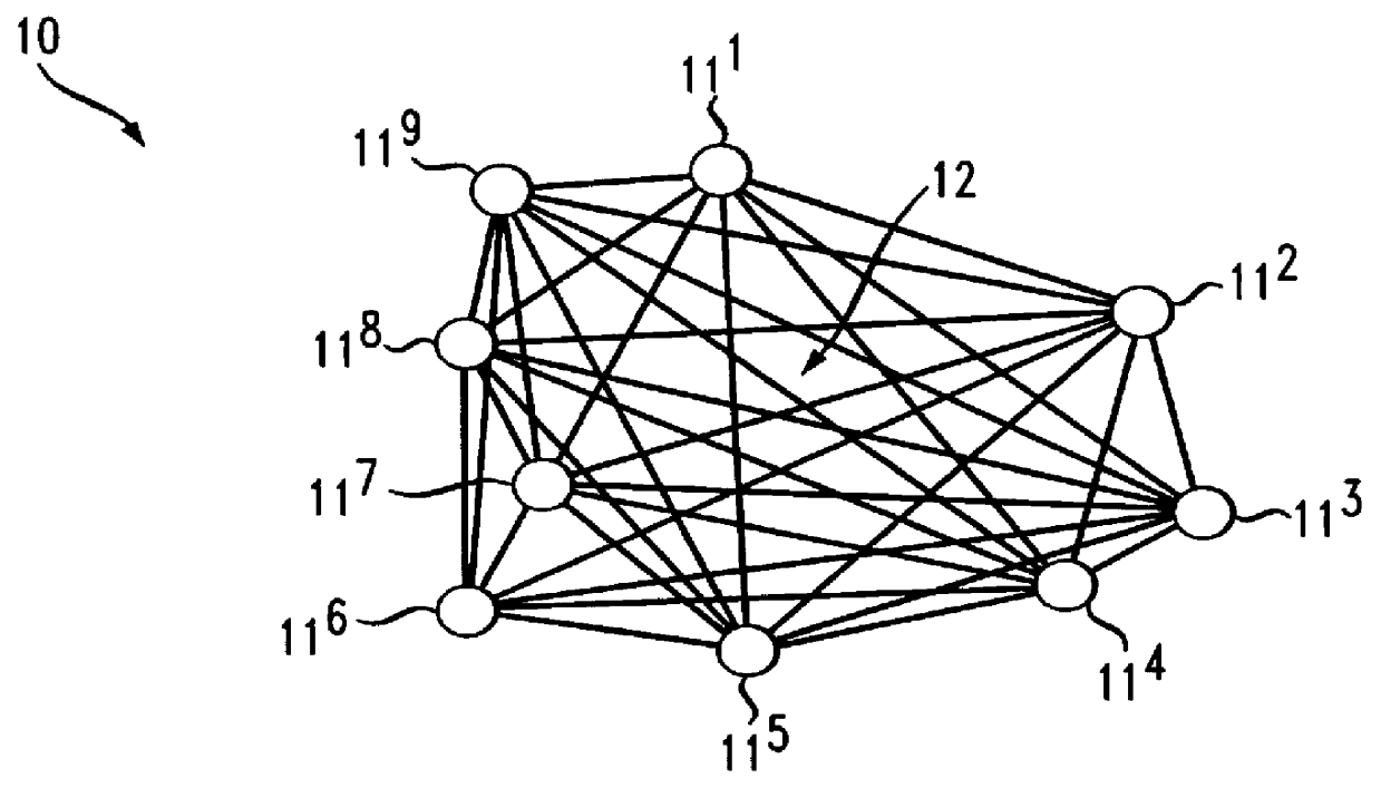
In FIG. 1 a prior art communication system 10 is shown including network switching centers 11 interconnected to other switching centers through transmission links 12. In one form, the network switches may be part of a Digital Access and Cross-Connect System (DACS). A DACS is a digital switching device for routing and switching T3 lines and Digital Signal, (DS3) portions of lines among multiple T-3 ports. The system performs all the functions of a normal switch, except that connections are typically set up in advance of the call, not together with the call as in most normal low band communication systems, for example, voice band and data. The DAC is a specialized type of high speed data channel switch.

The transmission lines 12 are typically of a T3 type which contain 28 T1 channels and are commonly referred to as a 45 megabit per second line capable of handling 672 voice conversations.

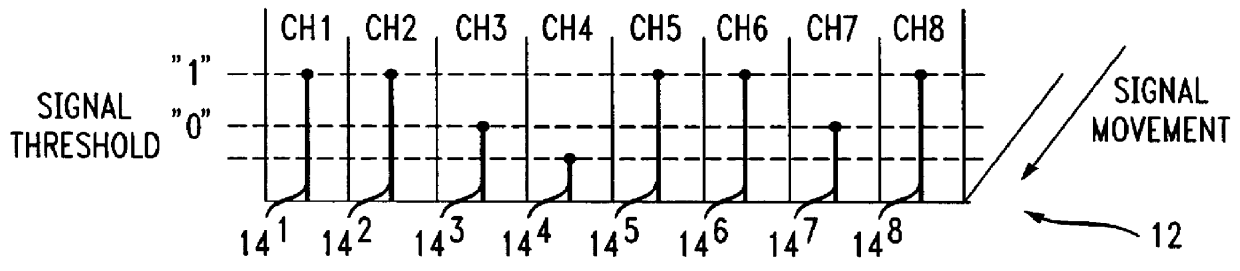
In FIG. 2 a portion of a transmission line 12 is shown containing channel 1 . . . , channel n, in wh...


PUM


Abstract

In switching centers serving multiple local access providers, a problem arises in detecting cable failure and identifying the provider of the failed cable connected between the switching center and remote terminals. A test circuit installed in each cable port of the switching center detects failed cables; identifies the operator of the failed cable, and designates the cable end at which the failure occurs. The test circuit includes a signal detector and a signal generator and monitor connected through a switching device to the cables. A data signal Ds is transmitted on the cables. When the detector recognizes a loss of a data signal Ds exceeding a threshold a failed cable has occurred at one end of the cable or the other. The switch is activated by the signal loss to connect the signal generator and monitor to determine at which cable end the cable has failed. A reference signal Rs is injected into a cable by the signal generator and monitor. If the data signal Ds on the failed cable matches the reference signal Rs in amplitude and phase, a cable failure is indicated at the near end of the cable detector. If the data signal Ds is degraded in amplitude and shifted in phase relative to the reference signal Rs, a cable failure is indicated at the far end of the cable.

Description

1. Field of the InventionThis invention relates to methods and apparatus for cable testing in communication systems. More particularly, the invention relates to methods and apparatus for detecting a failed cable end and operator of the cable connected between remote switching centers in communications systems.2. Description of the Prior ArtToday's communications systems include transmission paths, for example, T3 lines linked together by network switching centers serving multiple-access providers. In many instances, a network switching failure can be attributed to a bad or disconnected T3 cable interconnecting remote switching centers. One problem with such a failure is detecting and identifying the cable end at which the failure has occurred. Another problem is determining the access provider responsible for the failed cable and restoring service to the switching center.Prior art related to detecting and identifying faults in cables connected to remote switching centers includes th...

Claims


Application Information

Patent Timeline
Patent Type & Authority Patents(United States)
IPC IPC(8): H04B3/46H04M3/28H04M3/32
CPCH04B3/46H04M3/085H04M3/32H04M3/28H04M2207/08
Inventor VEDDER, MARK
Owner AMERICAN TELEPHONE & TELEGRAPH CO
Why Eureka
Try Eureka