Non-contact position sensor
- Summary
- Abstract
- Description
- Claims
- Application Information
AI Technical Summary
Problems solved by technology
Method used
Image

Examples
Embodiment Construction
Assume that:
Bias field (H.sub.B)=50 Gauss
Magnet induced field (H.sub.M) will vary + / -20% due to movement of magnet.
Therefore: ##EQU1##
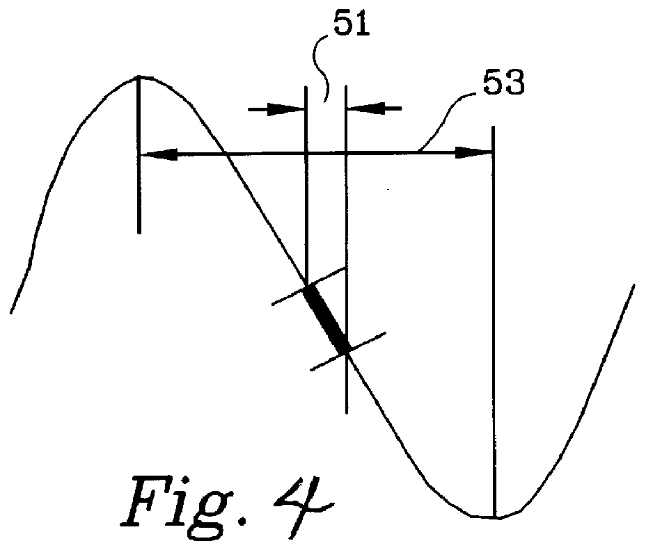
Thus by causing the magnet induced flux to vary from 40 gauss to 60 gauss the output signal would vary 11.6 degrees over a very linear portion of the output function.
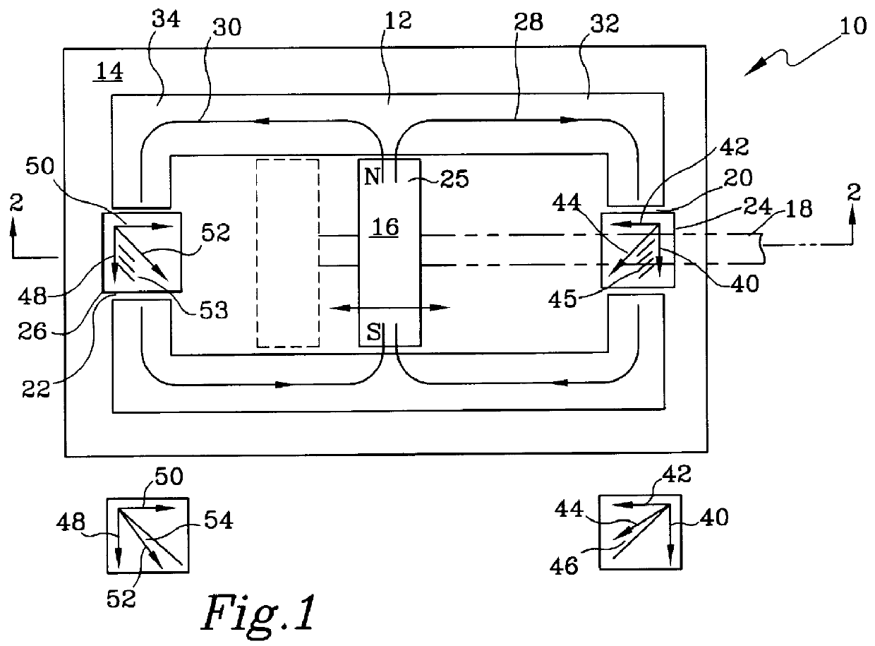
An alternate embodiment of non-contact position sensor 10 is shown in FIGS. 5 and 6 and includes a semi-permeable core 60 mounted on a substrate or base 62 and a magnet 64 connected to a movable member or shaft 68 so that magnet 64 may be rotated about an axis of shaft 68. Core 60 includes an air gap 70 and an air gap 72. A magnetic sensor 74 and a magnetic field sensor 76 are located in air gap 70 and air gap 72 respectively. Magnet 64 is a dipole magnet having a north pole and a south pole. Flux 78 from magnet 64 is guided by core 60 and divides along either a first path 80 or a second path 82 within core 60. Flux lines 84 are guided from a north pole along a right hand portion of core ...
PUM
 Abstract
Description
Claims
Application Information
 - R&D
- Intellectual Property
- Life Sciences
- Materials
- Tech Scout
- Unparalleled Data Quality
- Higher Quality Content
- 60% Fewer Hallucinations
Browse by: Latest US Patents, China's latest patents, Technical Efficacy Thesaurus, Application Domain, Technology Topic, Popular Technical Reports.
© 2025 PatSnap. All rights reserved.Legal|Privacy policy|Modern Slavery Act Transparency Statement|Sitemap|About US| Contact US: help@patsnap.com