CNC data correction method

a technology of nc data and correction method, which is applied in the direction of program control, total factory control, instruments, etc., can solve the problems of machining errors, machining errors, and delay in the servo system, so as to achieve high-accuracy machining and achieve the effect of avoiding machining errors

Inactive Publication Date: 2000-12-26
FANUC LTD
View PDF26 Cites 37 Cited by
  • Summary
  • Abstract
  • Description
  • Claims
  • Application Information

AI Technical Summary

Problems solved by technology

However, a delay in the servo system can be a hindrance in executing high-accuracy machining.
The delay in the servo system causes an actual tool path to deviate from the paths of machining blocks commanded by the NC data, thereby causing machining errors.
In the ordinary machining, these machining errors resulting from the follow-up delay are within an allowable range and thus are negligible.
In carryi...

Method used


Image

  • CNC data correction method
  • CNC data correction method
  • CNC data correction method

Examples


first embodiment

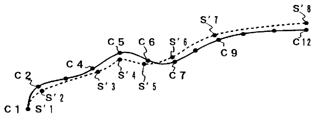
the present invention is characterized in that NC data is created according to a work shape that is composed of a spline curve created by a CAD system, and that machining is executed in accordance with the created NC data and the NC data is modified based on the machining errors occurred therein. As a result, modified NC data, when applied, produces extremely small machining errors.

(a) Description of Principle of NC Data Modification Method

The following is a description of the principle of an NC data modification method according to the first embodiment of the present invention.

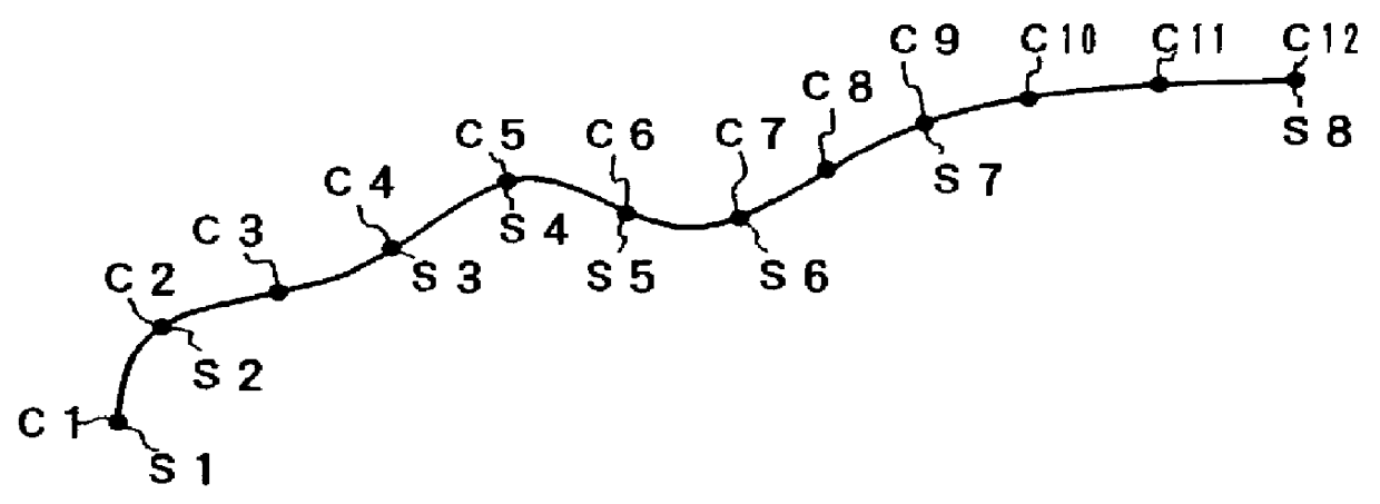
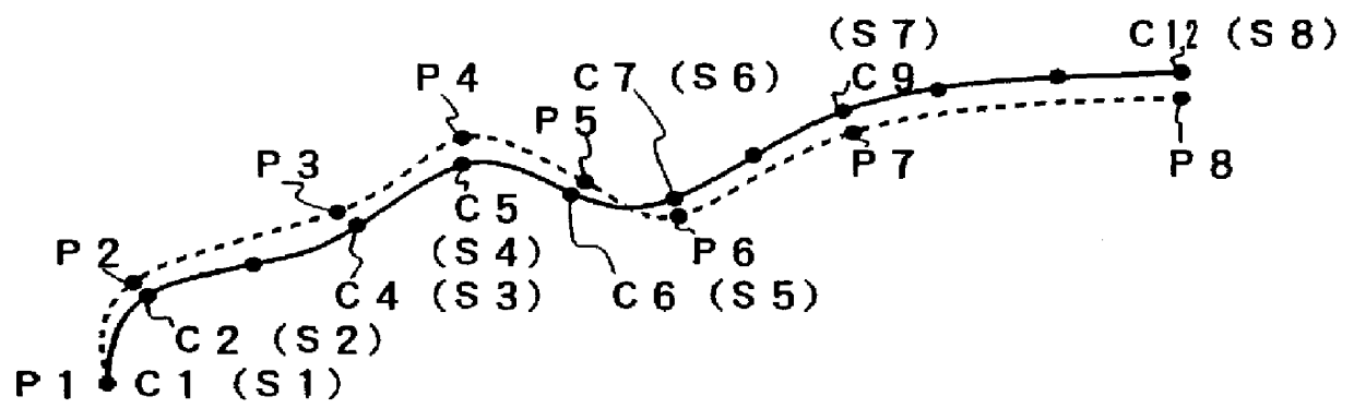
As shown in FIG. 1, CAD data for creating the NC data is defined as a group of points Cj(Xcj, Ycj, Zcj) (j=1, 2, 3 . . . ) on the spline curve. The NC data is created by defining this spline curve as a series of straight lines (segments connecting points Si and Si+1 in FIG. 2, as described later) with infinitesimal lengths.

It is determined whether or not a straight line that connects one point Cj and its subs...

second embodiment

B. Description of Second Embodiment

The table T1 of FIG. 5 is prepared by obtaining the current command position si(Xsi, Ysi, Zsi) (value in the current command position register before the command value for the distribution cycle concerned is added thereto), actual machine position Pi(Xpi, Ypi, Zpi) (value in the current position register), and current load value ti(Xti, Yti, Zti) (value estimated by the real current or observer), in the same manner as in the foregoing first embodiment. Then, a current command position s(Xs, Ys, Zs) corresponding to the starting point (ending point) Si of each block is obtained from the table T1, and the actual position Pi(Xpi, Ypi, Zpi) (value in the current position register) corresponding to the corresponding current command position s=Si(Xsi, Ysi, Zsi) and the current load value ti(Xti, Yti, Zti) are obtained to prepare a table similar to the table T2 of FIG. 6 (corresponding to Step a1). In this case, the CAD data is not used.

Then, a difference...


PUM


Abstract

PCT No. PCT/JP97/01089 Sec. 371 Date Nov. 26, 1997 Sec. 102(e) Date Nov. 26, 1997 PCT Filed Mar. 28, 1997 PCT Pub. No. WO97/37291 PCT Pub. Date Oct. 9, 1997Actual machining positions P1, P2, . . . corresponding to command positions S1, S2, S3 . . . of each block of NC data are obtained by trial machining. Positions that correspond symmetrically to the actual machining positions P1, P2, . . . with respect to the command positions S1, S2, S3 . . . of each block are obtained. Modified NC data are created with use of the symmetrical positions as modified command positions for each block. The modified NC data include correction values for modifying positional differences attributable to a delay in a servo system. Therefore, if machining is carried out in accordance with the modified NC data, the correction values and a follow-up delay attributable to the actual delay in the servo system cancel one another, so that a high-accuracy work shape can be obtained.

Description

1. Technical FieldThe present invention relates to a correction method for NC data for high-accuracy machining.2. Background ArtAfter move commands for servomotors for driving individual axes of a machine tool are given to a servo system in accordance with NC data, the servo system carries out servo processing, whereupon the servomotors for the individual axes are driven to execute machining. However, a delay in the servo system can be a hindrance in executing high-accuracy machining. The delay in the servo system causes an actual tool path to deviate from the paths of machining blocks commanded by the NC data, thereby causing machining errors.In the ordinary machining, these machining errors resulting from the follow-up delay are within an allowable range and thus are negligible. In carrying out special high-accuracy machining, however, the machining errors resulting from the follow-up delay are not negligible. In order to reduce the machining errors caused by the follow-up delay, ...

Claims


Application Information

Patent Timeline
IPC IPC(8): G05B19/41G05B19/4103G05B19/414G05B19/4155G05B19/4093
CPCG05B19/4103G05B19/414G05B19/4155G05B2219/33099G05B2219/34096G05B2219/50057G05B2219/35051G05B2219/36043G05B2219/36048G05B2219/41363G05B2219/35012Y02P90/02
Inventor KAMIGUCHI, MASAOMAEKAWA, SUSUMU
Owner FANUC LTD
Why Eureka
Try Eureka