
Isolation tool release mechanism

a technology of isolation tool and release mechanism, which is applied in the direction of drilling casings, wellbore/well accessories, pipes, etc., can solve the problems of unacceptably large amount of force required to pull the setting tool, tubing failure may occur prior to the vacuum or reduced pressure condition , to exist below the vacuum or reduced pressure condition

Inactive Publication Date: 2001-01-02
BJ SERVICES CO
View PDF3 Cites 248 Cited by
  • Summary
  • Abstract
  • Description
  • Claims
  • Application Information

AI Technical Summary

Problems solved by technology

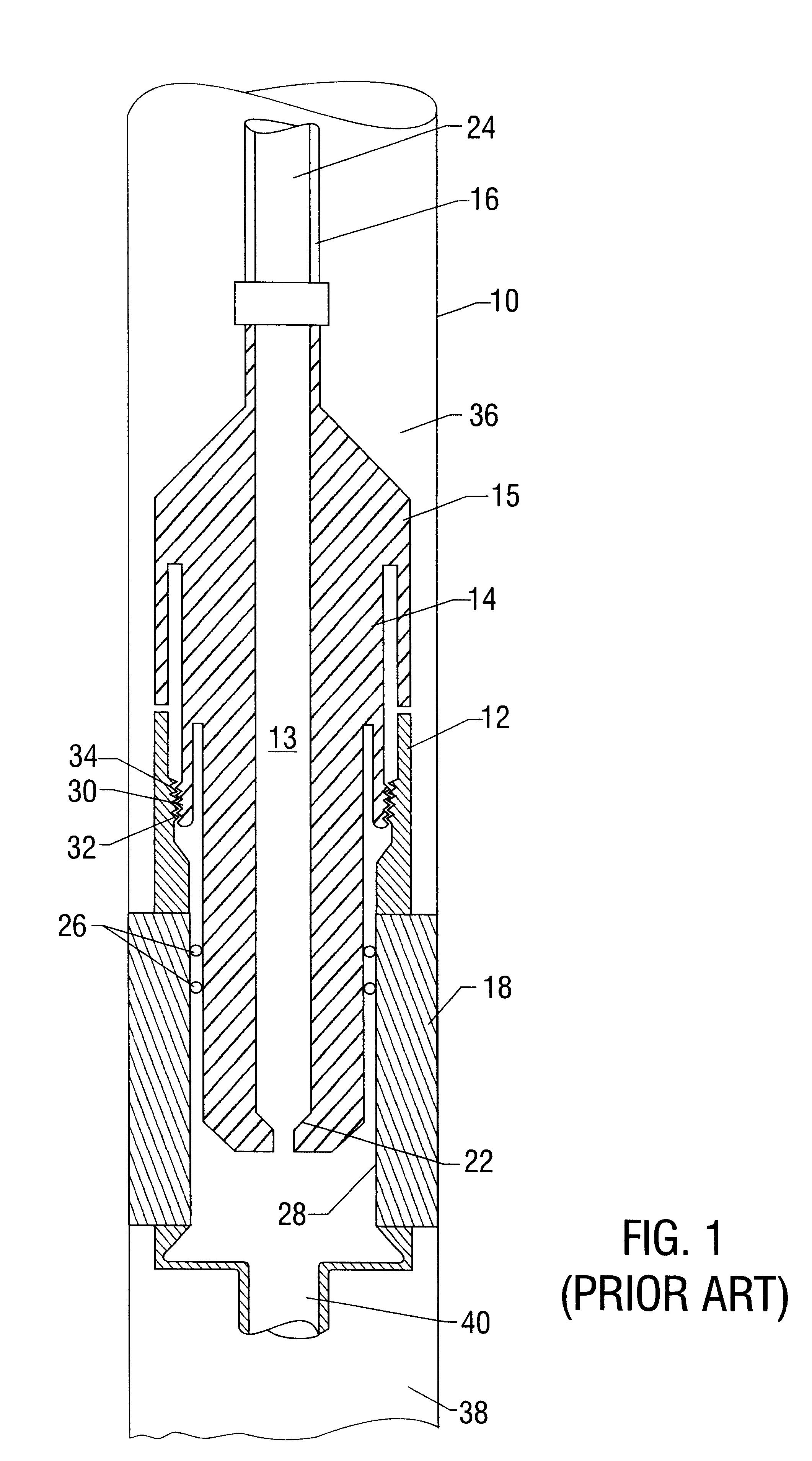
During these and other types of wellbore operations, when a isolation tool such as a packer or bridge plug is set at a point in a wellbore having no perforations open below the setting point, a setting tool when pulled from the isolation tool may cause a vacuum or reduced pressure condition to exist below the isolation tool relative to the pressure existing above the isolation tool.
Such a pressure differential typically acts on sealing elements or apparatus of the setting tool so that an unacceptably large amount of force may be required to pull the setting tool from is the isolation tool.
When the force required to pull the setting tool from the isolation tool exceeds the maximum allowable pulling force, for example of tubing used to set the isolation tool, tubing failure may occur prior to the point where the setting tool becomes unseated from the isolation tool.
Perforating or severing the tubing is undesirable because it may damage downhole completion assemblies leaving the isolation tool and / or setting tool in unusable condition, and even potentially "junking" the well.
In some cases, a sufficient pressure differential may be created during attempted pulling of a setting tool such that a collapse force is generated across the isolation tool components resulting in tool failure.
Undesirably high pressure differentials may also be created when pulling a setting tool out of an isolation tool even where open perforations exist below the isolation tool.
Such a problem may exist, for example, where the perforations are of limited entry into the formation, where a formation is very tight (or has very low permeability), and / or where the permeability of a perforated formation is damaged.

Method used


Image

  • Isolation tool release mechanism
  • Isolation tool release mechanism
  • Isolation tool release mechanism

Examples


Embodiment Construction

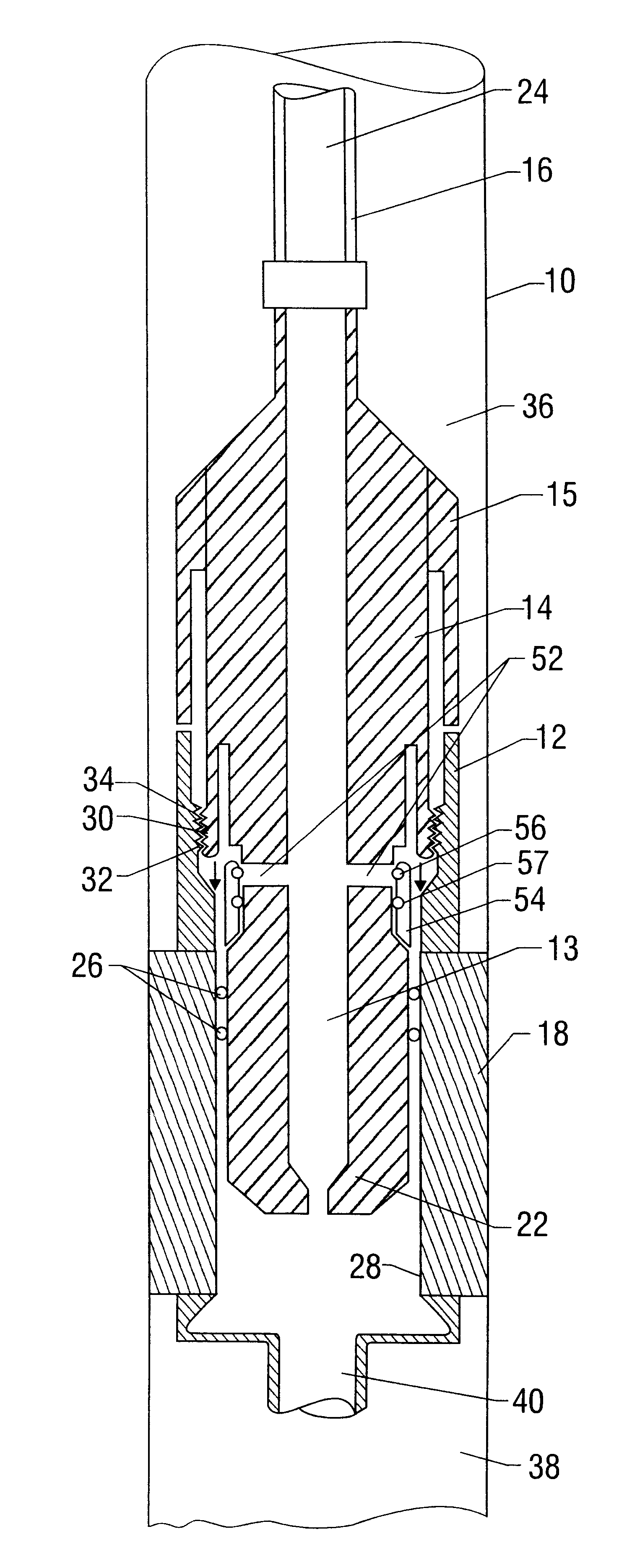
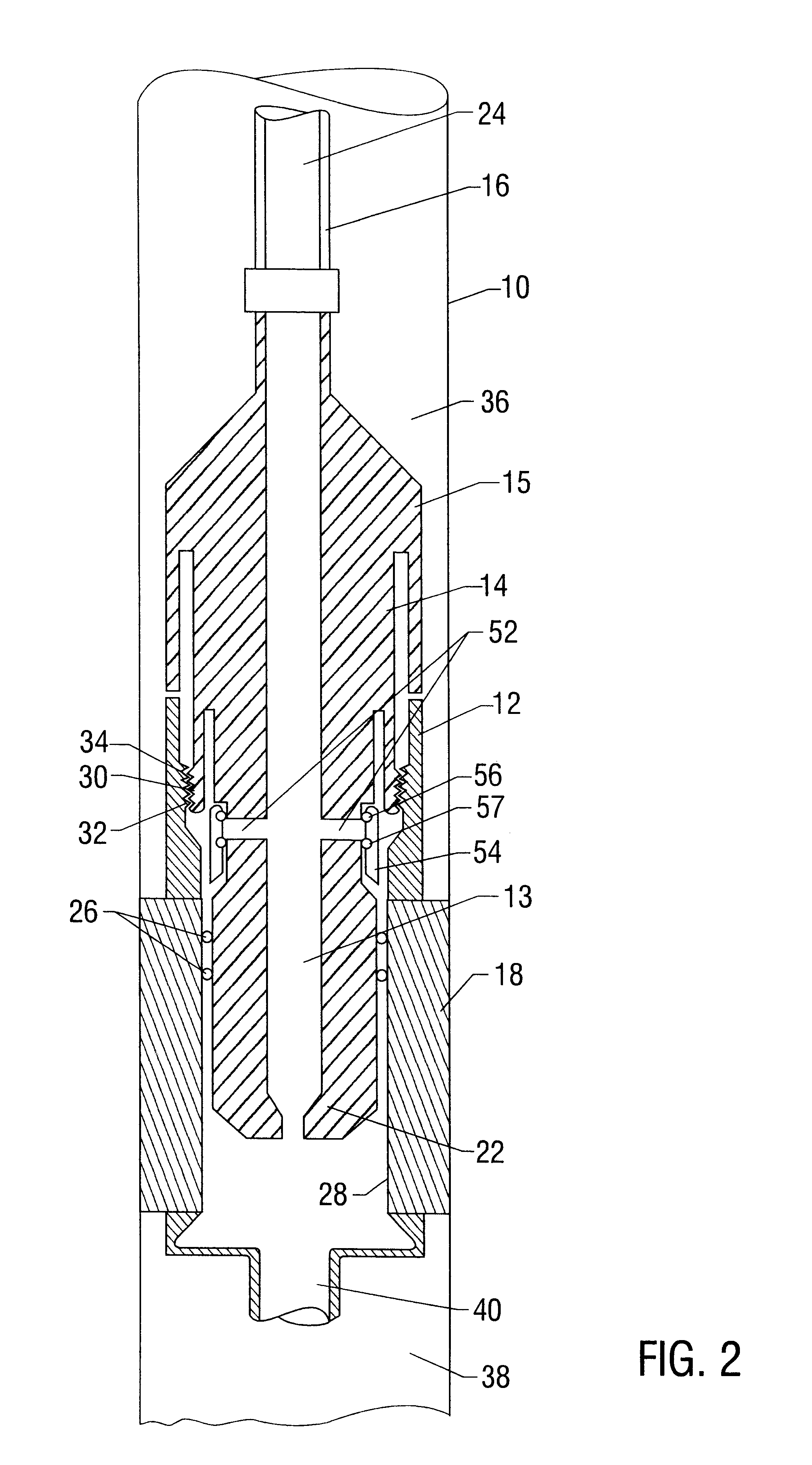
The disclosed method and apparatus are useful for, among other things, in setting and / or retrieving isolation tools such as packers or bridge plugs in wellbores in which a relatively high pressure differential exists above and below the isolation tool. In particular, the disclosed methods and apparatus include a release mechanism useful for setting and / or retrieving isolation tools in wellbores in which such conditions exist. Advantageously, embodiments of the disclosed release mechanism may include one or more pressure equalization ports or openings through which pressure may be selectively equalized above and below an isolation tool prior to removing, for example, a setting tool from the isolation tool. The disclosed release mechanism is typically configured for use in a setting and / or retrieving tool configuration designed to set or retrieve an isolation tool on a conduit, such as tubing or drill pipe, either mechanically or hydraulically. However, embodiments of the disclosed re...


PUM


Abstract

A release mechanism for use with setting wellbore isolation tools, such as packers or bridge plugs. The release mechanism typically includes a release piston which selectively isolates equalization ports extending from the interior to the exterior of a setting tool body. The release piston may be activated to allow equalization of pressure across the sealing elements of a set isolation tool, typically by applying pressure to the annular space above the isolation tool. The release mechanism may be used to allow a tool body (such as a setting or retrieving tool) to be removed from a set isolation tool under conditions in which high pressure differential exists across the isolation tool.

Description

1. Field of the InventionThis invention relates generally to methods and apparatus for well completions and, more particularly, to methods and apparatus for setting and / or releasing from isolation tools within a well. Specifically, this invention relates to methods and apparatus for equalizing pressure differentials existing across the seals of a well isolation tool, such as a packer or bridge plug, during tool setting operations.2. Description of Related ArtIn well completions, it is often desirable to isolate one or more sections of a well from another. For example, one completion zone may be isolated from another so that only one completion zone is open for production or injection at a time. Such isolation may be accomplished by the placement of one or more isolation tools, such as packers and / or bridge plugs, in the wellbore on either or both sides of one or more completion zones. Isolation tools are typically annular in shape and configuration. The sequence of production from, ...

Claims


Application Information

Patent Timeline
IPC IPC(8): E21B23/04E21B23/00E21B23/06
CPCE21B23/04E21B23/06E21B34/142
Inventor STOUT, GREGG W.MATTE, JAMES T.
Owner BJ SERVICES CO
Learn More