
Wheel luminaire

Inactive Publication Date: 2001-01-02
MARTINEZ MARVIN R +1
View PDF4 Cites 41 Cited by
  • Summary
  • Abstract
  • Description
  • Claims
  • Application Information

AI Technical Summary

Problems solved by technology

Unfortunately, however, the Leeman patent does not provide the ordinary artisan with guidance as to how mount this contact ring so that the wheel does not have to be modified.
Perhaps more importantly, Leeman does not provide the necessary guidance to avoid problems associated with the need to dissipate the heat generated by the friction associated with the constant rubbing of the brush against the contact ring.
A significant disadvantage of this system, aside from the need to provide hollow bolts, is that the contact ring is held against the wheel by means of the fasteners that hold the wheel against the wheel hub.
Accordingly, the stacking of a contact ring on top of an insulating material, which in turn is stacked on top of the wheel creates significant problems associated with the stability of the overall structure and the bending stresses introduced into the fasteners due to the distances introduced by the stacking of several components.
The Bell invention, however, suffers from the disadvantage that the contact ring or track must be made such that its radius matches the radius of the drum on which it is mounted.
Additionally, the use of an insulating material and a series of screws threaded directly into the brake drum can lead to serious fatigue or similar problems associated with the heating of the brake drum during operation.
This arrangement solves many of the thick stack up problems associated with the Brown device, but is severely limited in that the structure on which the Bradway device attaches has become increasingly unpopular in modern automobiles.
The similarities of the Senseman structure and the Bradway structure cause similar limitations in the Senseman device as are found in the Bradway device.
There remains a need for an illumination system that is light weight, and thus provides little opportunity for creating an imbalance on the wheel structure.

Method used


Image

  • Wheel luminaire
  • Wheel luminaire
  • Wheel luminaire

Examples


Embodiment Construction

While the invention will be described and disclosed here in connection with certain preferred embodiments, the description is not intended to limit the invention to the specific embodiments shown and described here, but rather the invention is intended to cover all alternative embodiments and modifications that fall within the spirit and scope of the invention as defined by the claims included herein as well as any equivalents of the disclosed and claimed invention.

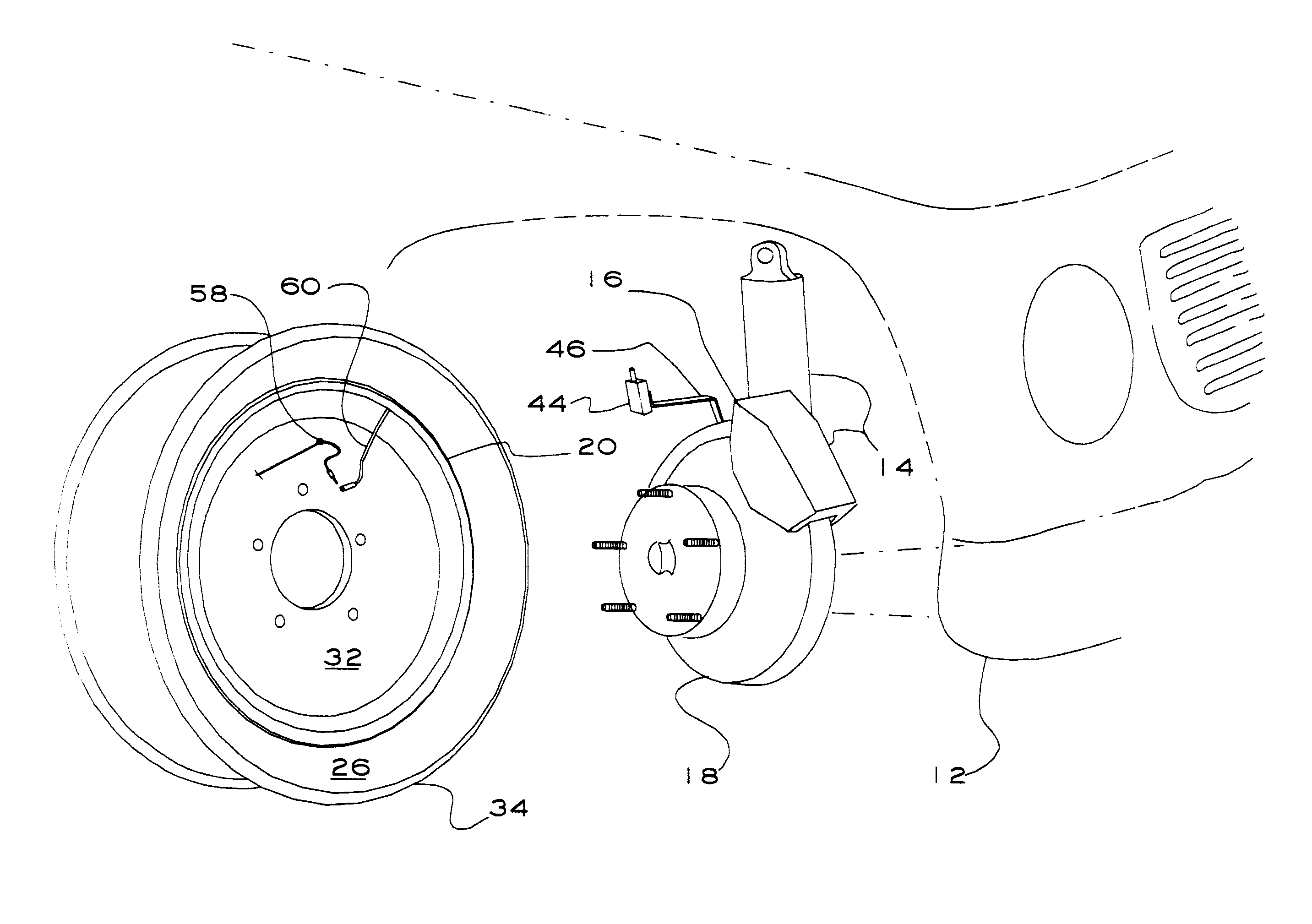
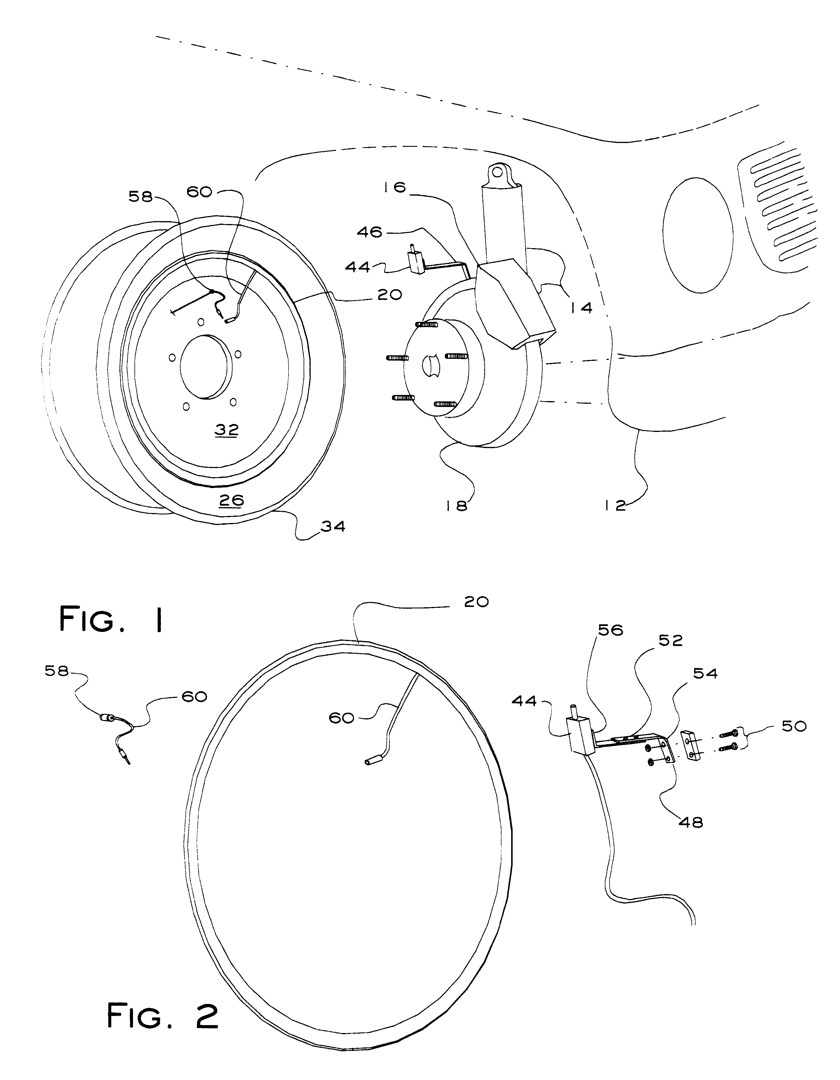
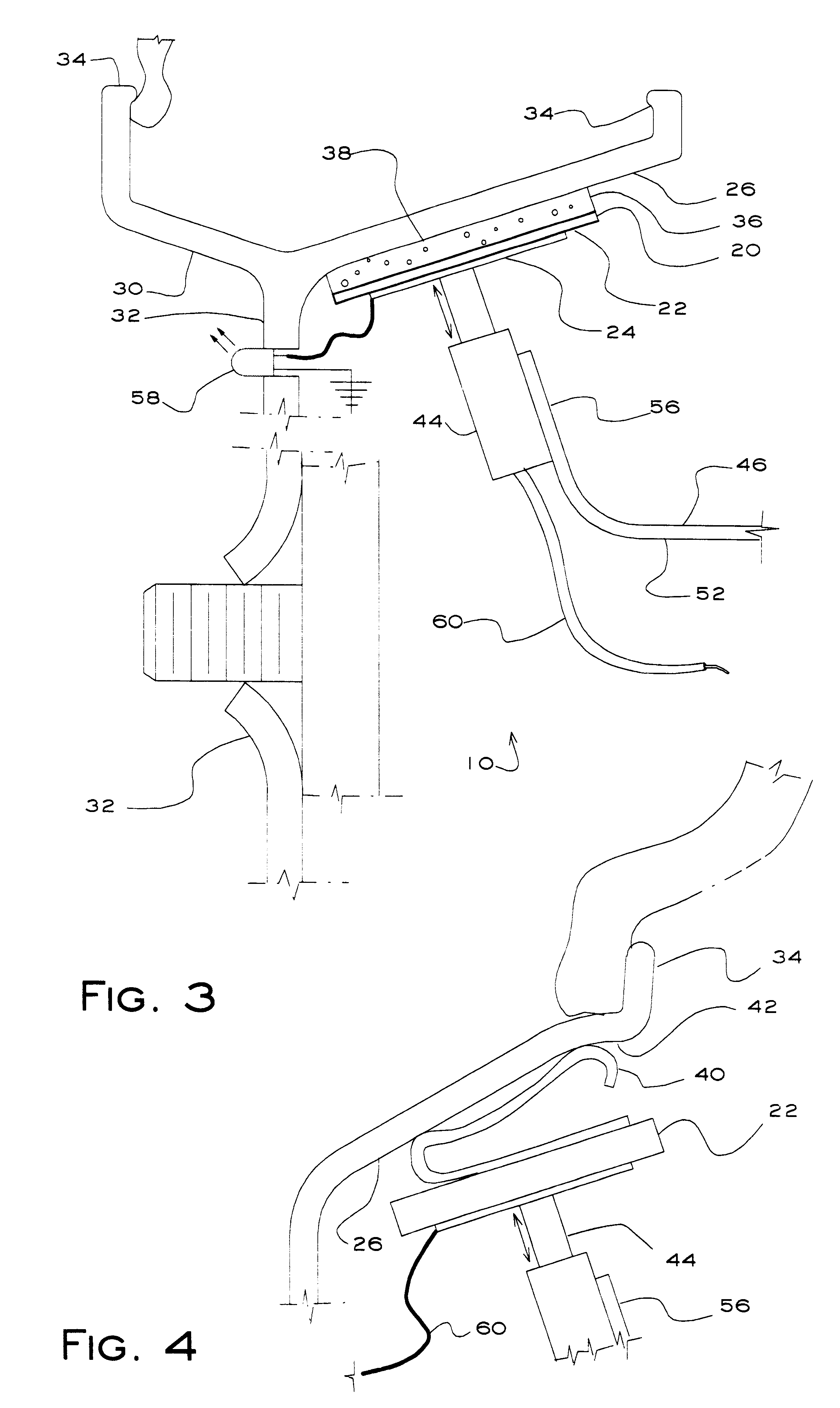
Turning now to FIG. 1 where an illuminated wheel system 10 for use with an automobile 12 has been illustrated. It is contemplated that the system 10 will be used in conjunction with a vehicle which has an electrical power source as commonly found on automobiles. However, it is important to note that it is contemplated that the disclosed novel assemblies can be used on other applications, for example on toy cars, bicycles and the like, and even other rotating devices, such as electric fans and the like.

In a highly preferre...


PUM


Abstract

A system for illuminating a wheel on a vehicle, the wheel having a concave area adapted for mounting around a wheel hub attached to stationary structure on the vehicle, the vehicle having an electrical power source. The system includes a contact ring that includes a circular backing ring of an electrically insulating material and a layer of electrically conductive material over the backing ring. The contact ring is flexibly supported from the concave area of the wheel where a contact brush mounted from the stationary structure of the vehicle makes contact with the layer of electrically conductive material on the contact ring. At least one electrical light emitting device is electrically connected to the layer of electrically conductive material on the contact ring, so that electrical power from the power source reaches the light emitting device through the contact brush and through the contact ring.

Description

(a) Field of the InventionThis invention generally relates to a system for illuminating rotating objects. More particularly, but not by way of limitation, to a system for illuminating wheels and the like.(b) Discussion of Known ArtThe appeal of illuminating rotating objects, such as the wheel of a vehicle, has long been recognized. Accordingly, many devices have been developed to meet this need to provide the pleasing appearance of rotating illumination on wheels or the like. One such device is taught in U.S. Pat. No. 1,539,394 to Leeman. The Leeman patent discloses the use of a contact ring which is permanently attached to the wheel of a vehicle. Unfortunately, however, the Leeman patent does not provide the ordinary artisan with guidance as to how mount this contact ring so that the wheel does not have to be modified. Perhaps more importantly, Leeman does not provide the necessary guidance to avoid problems associated with the need to dissipate the heat generated by the friction a...

Claims


Application Information

Patent Timeline
IPC IPC(8): B60Q3/00B60Q3/04
CPCB60Q1/326Y10S362/80
Inventor MARTINEZ, MARVIN R.MARTINEZ, EDWARD
Owner MARTINEZ MARVIN R
Learn More