
Swing type machine and method for setting a safe work area and a rated load in same

a work area and rated load technology, applied in the direction of load-engaging elements, safety gear, transportation and packaging, etc., can solve the problems of limited capacity of lifting work particularly at an obliquely front or obliquely rear position, and the extent of the limitation of lifting work

Inactive Publication Date: 2001-01-09
KOBE STEEL LTD
View PDF6 Cites 117 Cited by
  • Summary
  • Abstract
  • Description
  • Claims
  • Application Information

AI Technical Summary

Problems solved by technology

In a conventional crane or the like, however, a certain limit work radius, i.e., the smaller work radius between a minimum value of a limit work radius which depends on strength and a minimum value of a limit work radius which depends on stability, is established throughout the whole circumference, so the hoisting work particularly at an obliquely front position or an obliquely rear position is limited to a greater extent than necessary and hence the capacity thereof is not fully exhibited.
But this work area deformation takes into account only such non-uniform protrusion of outrigger jacks.

Method used


Image

  • Swing type machine and method for setting a safe work area and a rated load in same
  • Swing type machine and method for setting a safe work area and a rated load in same
  • Swing type machine and method for setting a safe work area and a rated load in same

Examples


Embodiment Construction

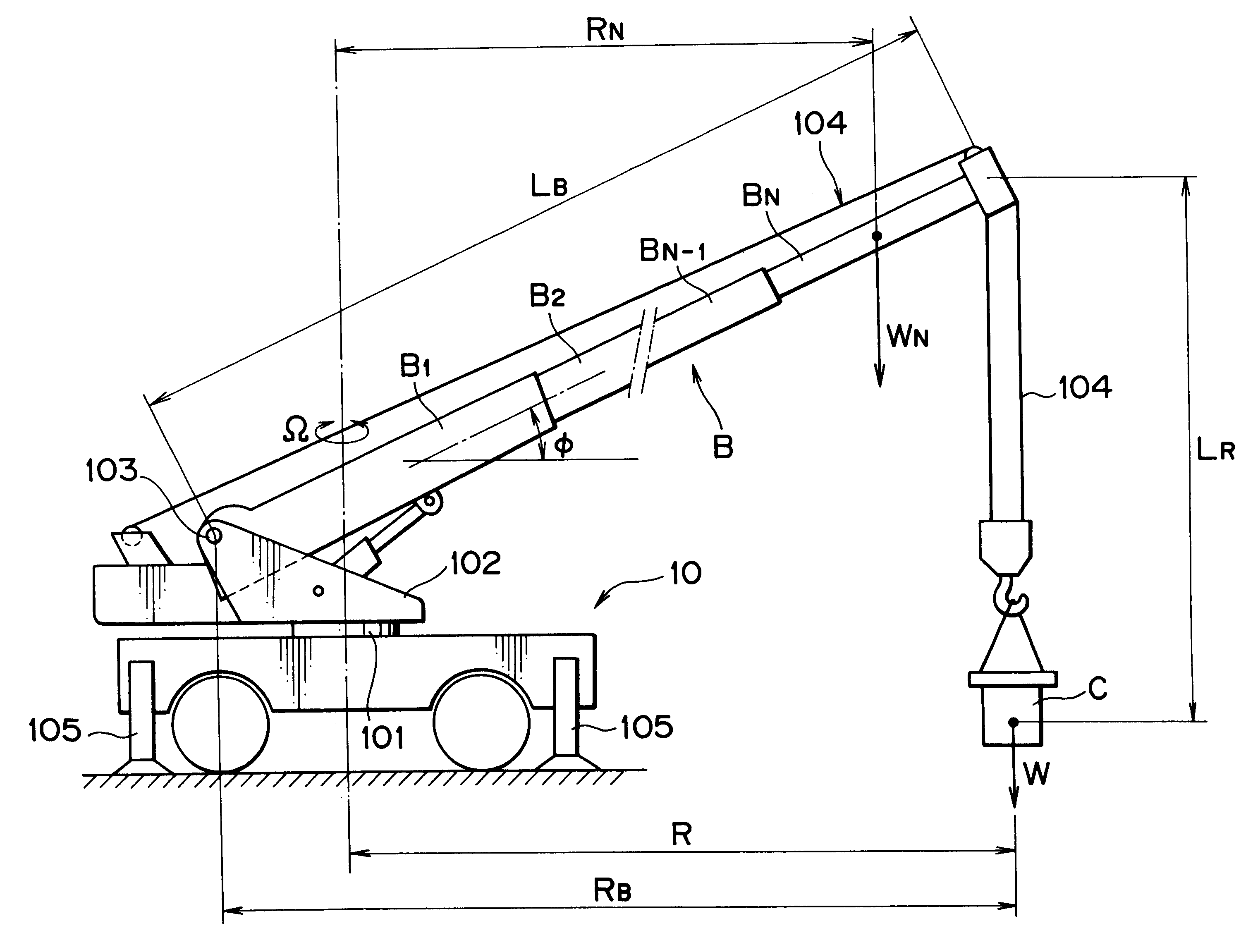
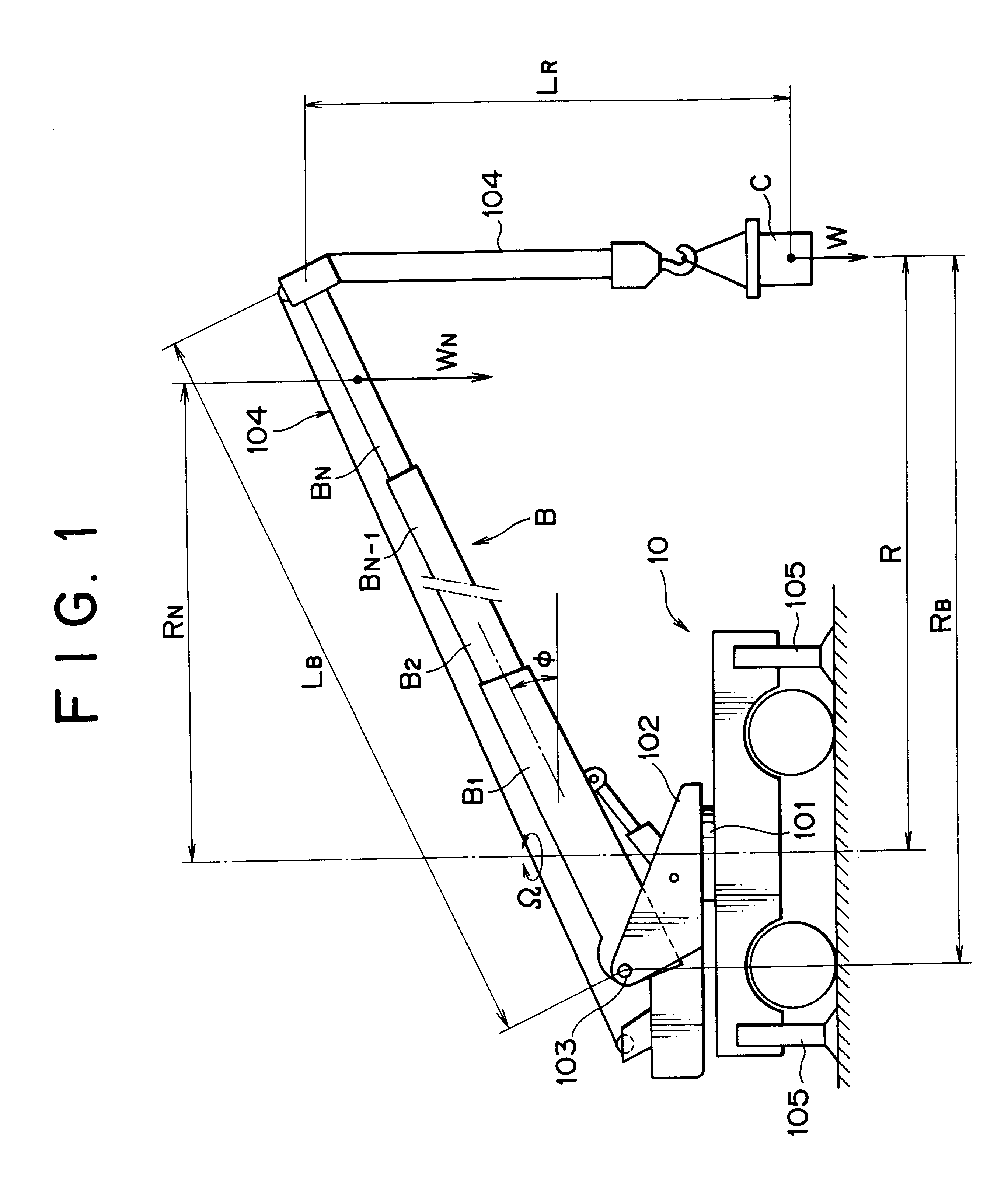
A preferred embodiment of the present invention will be described hereinunder with reference to the accompanying drawings. Although a crane is disclosed herein as an example of a swing type work machine, the present invention is applicable to various work machines provided with a swing member.

A crane 10 shown in FIG. 1 is provided with a swing frame 102 which is swingable about a vertical swing shaft 101, and a boom B comprising N number of boom members B1 to BN and capable of expansion and retraction is attached to the swing frame 102. The boom B is constituted so as to be pivotable (capable of rise and fall) about a horizontal pivot shaft 103, and an article C is suspended at the tip (boom point) of the boom B through a hoisting rope 104. In the following description it is assumed that Bn (n=1, 2, . . . , N) indicates the n.sup.th boom member counted from the swing frame 102 side.

At the four, front, rear and right, left corners of a lower frame of the crane 10 are disposed outrigg...


PUM


Abstract

A method for setting a safe work area and a rated load in a swing type work machine, as well as a swing type work machine which utilizes the said method, are disclosed. An area where a strength-based safe work area which is established taking the strength of a swing member into account and a stability-based safe work area which is established taking the stability of the work machine into account overlap each other, is set as a safe work area to be used actually. Likewise, out of a strength-based rated load which is set taking the strength of the swing member into consideration and a stability-based rated load which is set taking the stability of the work machine into consideration, the lower one is set as a rated load to be used actually. Using the safe work area and rated load thus obtained, there are made a safety control and an appropriate display. According to this method, in a swing type work machine such as a crane, it is possible to establish a safe work area and a rated load both matching the actual hoisting capacity of the work machine.

Description

1. Field of the InventionThe present invention relates to a swing type work machine such as a crane having a swing member provided with a boom or the like, as well as a method for setting a safe work area and a rated load according to a working state of the machine.2. Description of the Related ArtGenerally, in such a swing type work machine as above it is required, from the standpoint of safety, to prevent breakage and tipping during a swing work of the machine, and as means for satisfying such requirement it is very important to properly set a rated load and a safe work area, or a limit working radius, for operating the machine safely.In the above rated load and safe work area there are included a strength-based rated load (safe work area) which is set taking the strength of each component into account and a stability-based rated load (safe work area) which is set taking the stability of the work machine into account. In determining the former, i.e., strength-based rated load (saf...

Claims


Application Information

Patent Timeline
Patent Type & Authority Patents(United States)
IPC IPC(8): B66C23/00B66C23/90B66C23/88B66C23/94
CPCB66C23/905B66C23/00
Inventor YOSHIMATSU, HIDEAKI
Owner KOBE STEEL LTD
Learn More