
Diaphragm actuated pressure relief valve with pressure balanced outlet and fail-safe operation

a pressure relief valve and diaphragm technology, applied in the direction of valve operating means/releasing devices, functional valve types, transportation and packaging, etc., can solve the problems of affecting the opening point of the valve, the discharge port of two such commercial valves is unbalanced against the outlet pressure, and the valve cannot relieve the full rated capacity

Inactive Publication Date: 2001-01-16
LIGH J YEN
View PDF25 Cites 17 Cited by
  • Summary
  • Abstract
  • Description
  • Claims
  • Application Information

AI Technical Summary

Problems solved by technology

The outlet ports of two such commercial valves are unbalanced against outlet pressure, i.e., the opening point of the valves are affected (changed) by the amount of pressure or vacuum on the outlet side due to the valve seat being biased to the outlet pressure.
If the diaphragm of either valve ruptures, the spring will keep the valve closed and it will not be able to relieve the full rated capacity of the valve.
If the main diaphragm ruptures, the spring will keep the valve closed and it will not be able to relieve the full rated capacity of the main valve.
Therefore a ruptured main diaphragm can be hazardous and compromise the safety of the system that the valve is intended to protect by not being able to relieve the unwanted pressure build-up.
Prior designs of weight or spring loaded pressure relief valves are not able to open very wide at relatively small overpressures because when the valve opens and relieves, the full tank pressure is not communicated to the sensing chamber or seat due to pressure drops along the sensing path.
U.S. Pat. No. 5,845,675 discloses a diaphragm / spring operated pressure relief valve having a sensing passage of substantially the same flow area as the outlet orifice of the valve whereby failure of either diaphragm results in "fail open" configuration.

Method used


Image

  • Diaphragm actuated pressure relief valve with pressure balanced outlet and fail-safe operation
  • Diaphragm actuated pressure relief valve with pressure balanced outlet and fail-safe operation
  • Diaphragm actuated pressure relief valve with pressure balanced outlet and fail-safe operation

Examples


Embodiment Construction

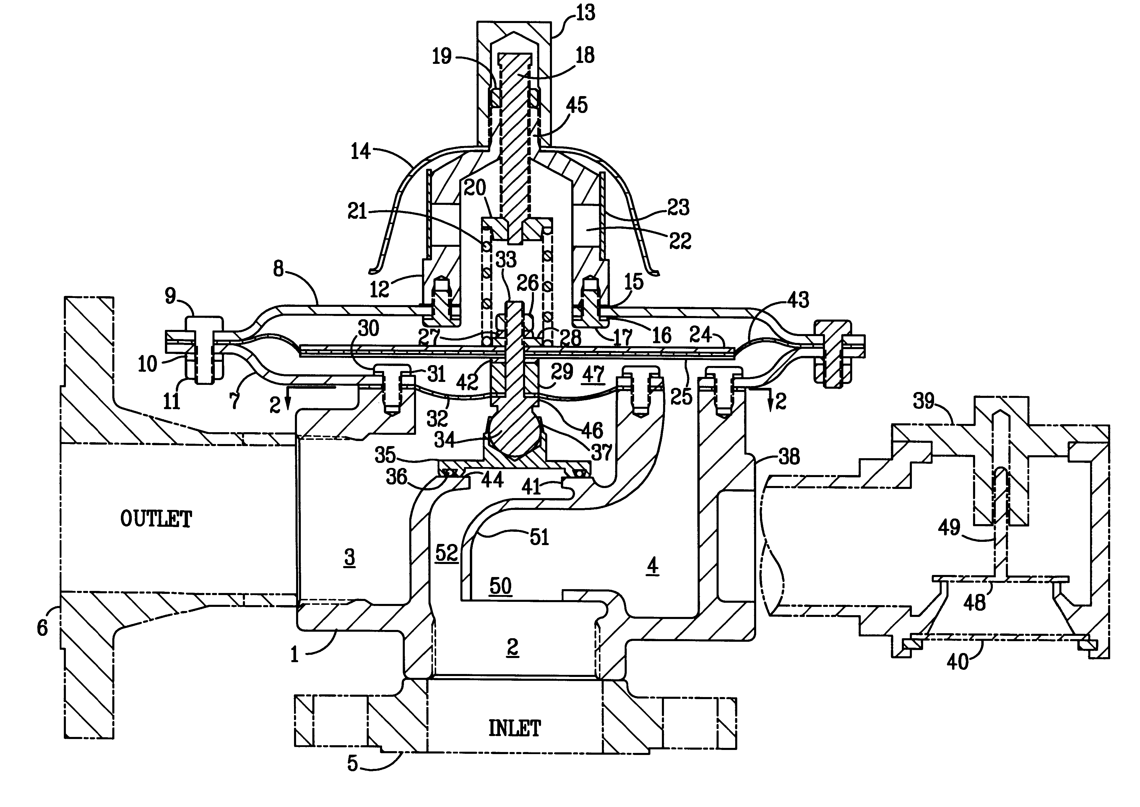
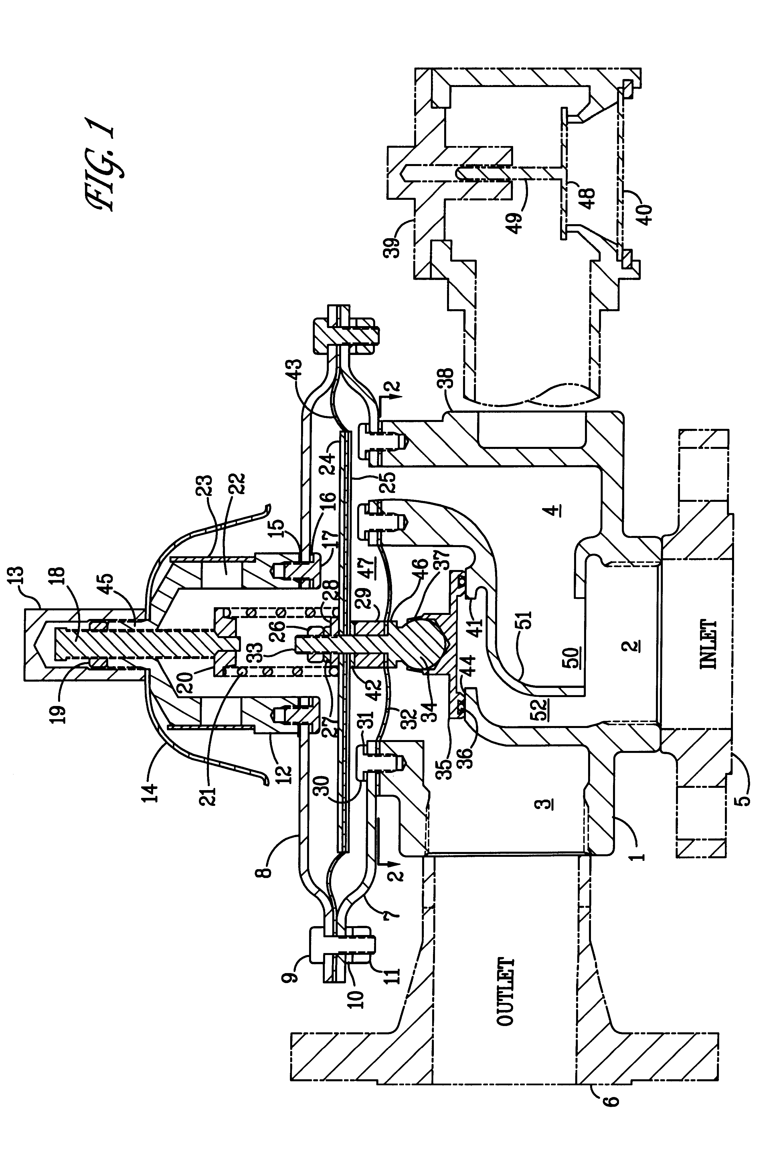
A detailed description of a preferred embodiment is provided by reference to FIG. 1, which shows an elevational view in partial cross section of one embodiment of the present diaphragm / spring actuated pressure relief valve or back-pressure regulator.

The valve body 1 has an inlet 2, an outlet 3 and sensing / vacuum passageway positioned between inlet 2 and the underside of sensing diaphragm 43. The sensing diaphragm is mounted by clamping it about its periphery between upper diaphragm case 8 and lower diaphragm case 7 which are secured together by bolts 9, lockwashers 10 and nuts 11, spaced around their circumferences. The diaphragm case is mounted to body 1 by bolts 30 and lockwashers 31 through lower diaphragm case 7.

FIG. 1 shows an optional flange 6 welded to the outlet and a similar optional flange 5 welded onto inlet 2. Other means of attachment (not shown) would include a threaded nipple.

A spring bonnet 12 having atmospheric openings 22 is mounted to the upper diaphragm case 8 by...


PUM


Abstract

A diaphragm / spring operated pressure relief valve having a sensing passage of substantially the same flow area as the outlet orifice of the valve whereby failure of either diaphragm results in "fail open" configuration with the addition of a sensing inlet shroud located to capture the total pressure at the inlet and channel it to the sensing chamber to allow the valve to relieve full rated capacity in the event the sensing diaphragm is ruptured.

Description

1. Field of the InventionThe present invention relates to a diaphragm / spring actuated pressure relief valve or back-pressure regulator that is pressure balanced against the outlet pressure for use on tanks where the outlet may be exposed to a pressure or vacuum that can vary in magnitude having improved pressure sensing.2. Related ArtThere are many types of diaphragm / spring actuated pressure relief valves.The outlet ports of two such commercial valves are unbalanced against outlet pressure, i.e., the opening point of the valves are affected (changed) by the amount of pressure or vacuum on the outlet side due to the valve seat being biased to the outlet pressure. If the diaphragm of either valve ruptures, the spring will keep the valve closed and it will not be able to relieve the full rated capacity of the valve. The most that one of these valves can relieve is the amount that can flow through the small passageway(s) that leads to the diaphragm chamber. In the other valve the maximu...

Claims


Application Information

Patent Timeline
Patent Type & Authority Patents(United States)
IPC IPC(8): F16K17/02F16K17/16F16K17/04F16K17/08
CPCF16K17/085F16K17/16Y10T137/7781
Inventor LIGH, J. YEN
Owner LIGH J YEN
Learn More