Stretch resistant embolic coil with variable stiffness

a coil and variable stiffness technology, applied in the field of embolic coils, can solve the problems of difficult, if not impossible, to retrieve the coil or reposition the coil, and difficulty in guiding the catheter through the vasculature of the body

Inactive Publication Date: 2001-01-30
CODMAN & SHURTLEFF INC
View PDF36 Cites 211 Cited by
  • Summary
  • Abstract
  • Description
  • Claims
  • Application Information

AI Technical Summary

Problems solved by technology

With these placements systems there is very little control over the exact placement of the coil since the coil may be ejected to a position some distance beyond the end of the catheter.
As is apparent, with these latter systems, when the coil has been released from the catheter it is difficult, if not impossible, to retrieve the coil or to reposition the coil.
One problem with this type of coil placement system which utilizes a pusher wire which extends through the entire length of the catheter and which is sufficiently stiff to push an attachment ball out of engagement with the socket at the distal end of the catheter is that the pusher wire inherently causes th

Method used


Image

  • Stretch resistant embolic coil with variable stiffness
  • Stretch resistant embolic coil with variable stiffness
  • Stretch resistant embolic coil with variable stiffness

Examples


Embodiment Construction

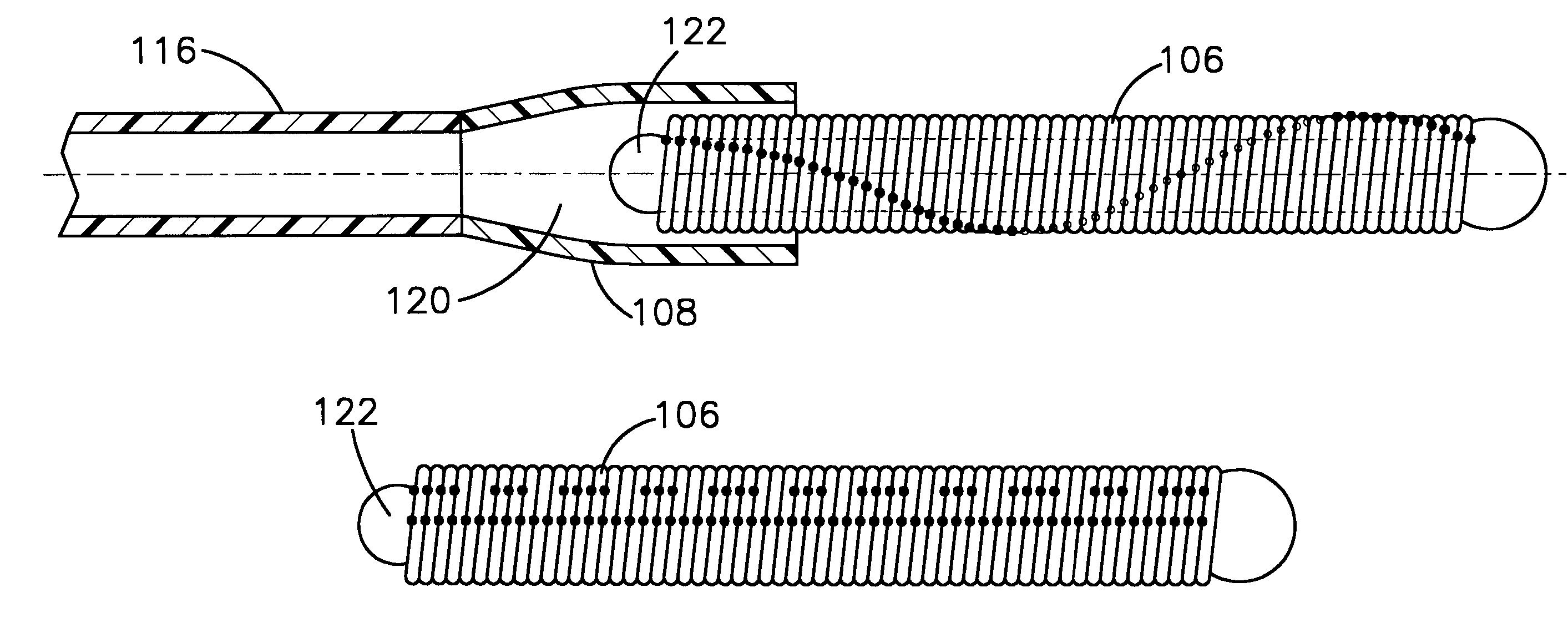
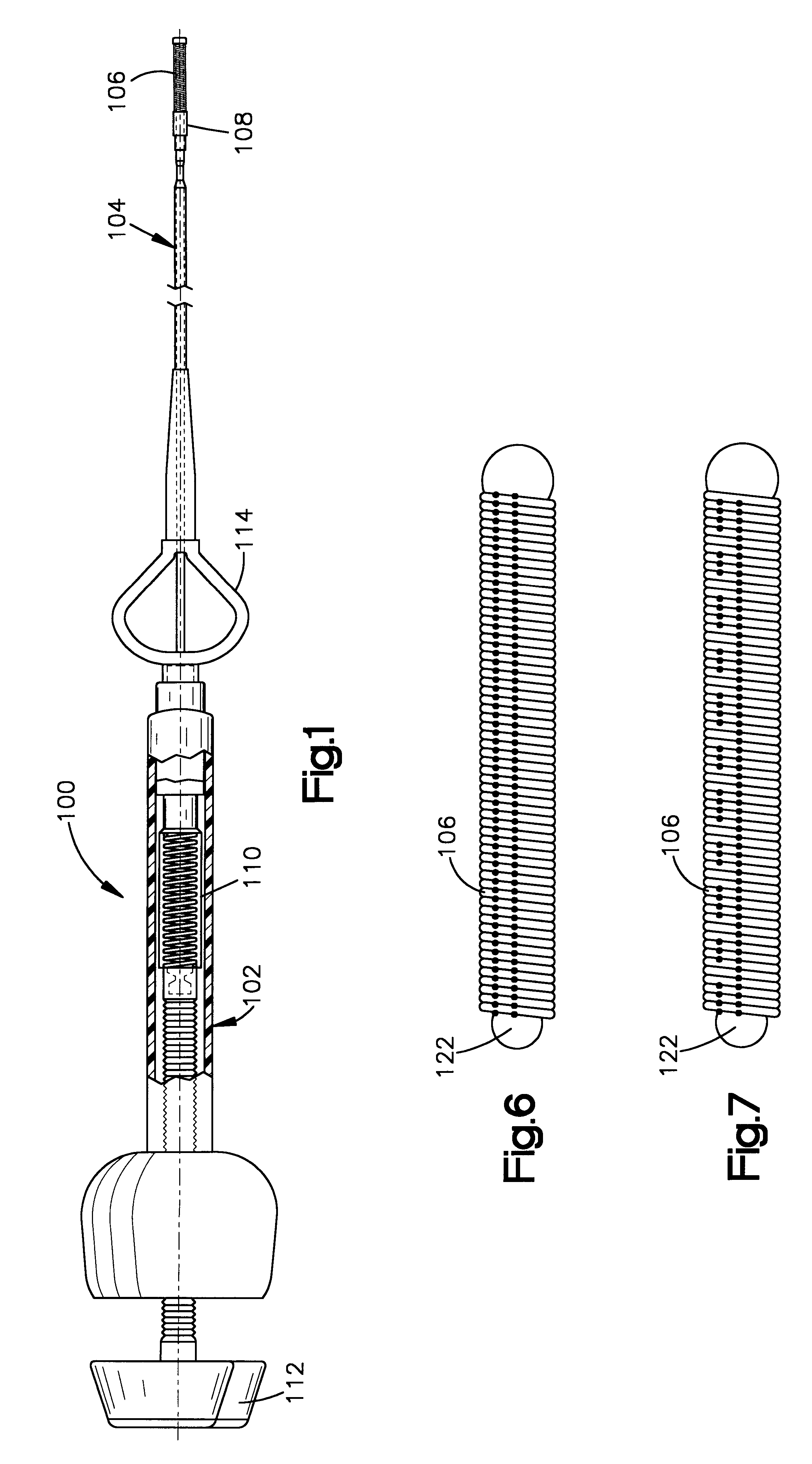
FIG. 1 generally illustrates the vascular occlusive coil deployment system 100 which is comprised of a hydraulic injector or syringe 102, coupled to the proximal end of a catheter 104. An embolic coil 106 is disposed within the lumen of the distal end 108 of the catheter. The proximal end of the coil 106 is tightly held within the lumen of the distal section 108 of the catheter 104 until the deployment system is activated for release of the coil. As may be seen, the syringe 102 includes a threaded piston 110 which is controlled by a handle 112 for infusing fluid into the interior of the catheter 104. Also as illustrated, the catheter 104 includes a winged hub 114 for connection of the catheter 104 to a syringe or other hydraulic injector.

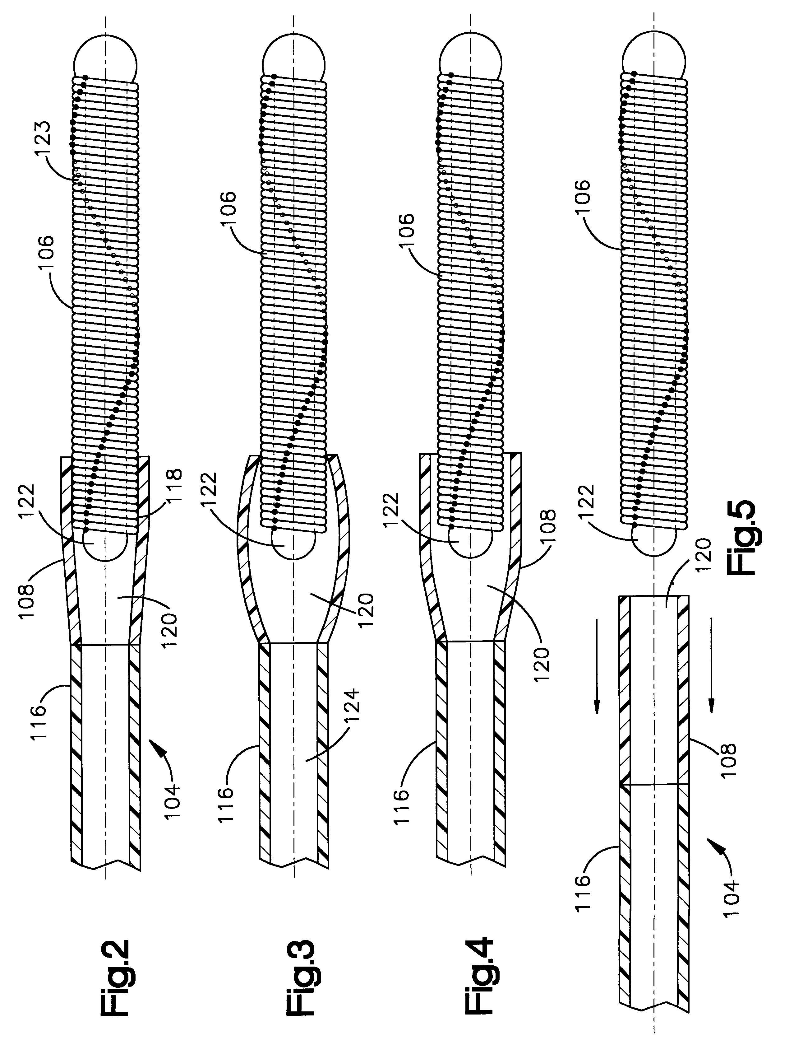
FIG. 2 illustrates in more detail the distal end of the catheter 104. The catheter 104 includes a proximal section 116 and the distal section 108. The proximal section 118 of the embolic coil 106 is disposed within the distal section 108 of the cath...


PUM


Abstract

An embolic coil which may be placed at a preselected location within a vessel comprising a helically wound coil in which various combinations of adjacent turns are spot welded together to create a stretch resistant coil of a preselected flexibility.

Description

1. Field of the InventionThe present invention relates to an embolic coil which may be placed at a preselected location within a vessel of the human body, and more particularly, relates to an embolic coil which is stretch resistant but which may be modified to vary the stiffness, or flexibility, of the coil.2. Description of the Prior ArtFor many years flexible catheters have been used to place various devices within the vessels of the human body. Such devices include dilatation balloons, radiopaque fluids, liquid medications and various types of occlusion devices such as balloons and embolic coils. Examples of such catheter devices are disclosed in U.S. Pat. No. 5,108,407, entitled "Method And Apparatus For Placement Of An Embolic Coil"; U.S. Pat. No. 5,122,136, entitled, "Endovascular Electrolytically Detachable Guidewire Tip For The Electroformation Of Thrombus In Arteries, Veins, Aneurysms, Vascular Malformations And Arteriovenous Fistulas." These patents disclose devices for de...

Claims


Application Information

Patent Timeline
IPC IPC(8): A61B17/12
CPCA61B17/12022A61B17/12154
Inventor DIAZ, ROBERTOJONES, DONALD K.NAGLREITER, BRETT E.
Owner CODMAN & SHURTLEFF INC
Why Eureka
Try Eureka