Apparatus and method for parallel rendering of image pixels

a technology of image pixels and rendering methods, applied in the direction of maintaining head carrier alignment, multiple processing units, instruments, etc., can solve the problems of difficult rendering in the definition of subpixel levels, and the time required for processing is not shortened, so as to achieve the effect of shortened time for rendering polygons

Inactive Publication Date: 2001-02-06
SONY CORP
View PDF9 Cites 102 Cited by
  • Summary
  • Abstract
  • Description
  • Claims
  • Application Information

AI Technical Summary

Benefits of technology

Accordingly, it is an object of the present invention to provide a rendering system and a rendering method which allow the time required for rendering polygons to be shortened and to render in the definition of sub-pixel level by providing a plurality of rendering circuits.

Problems solved by technology

However, when the display screen is divided as such, there has been a problem that when a polygon to be rendered is contained only within an area allocated to any one of the rendering circuits for example, a time required for processing it is not shortened even though the plurality of rendering circuits are provided because the rendering process is implemented on the polygon only by that one rendering circuit.
There has been also another problem that although it is conceivable to implement an interleave process for implementing the rendering process by allocating pixels per predetermined number to each rendering circuit, it is difficult to render in the definition of sub-pixel level.

Method used


Image

  • Apparatus and method for parallel rendering of image pixels
  • Apparatus and method for parallel rendering of image pixels
  • Apparatus and method for parallel rendering of image pixels

Examples


Embodiment Construction

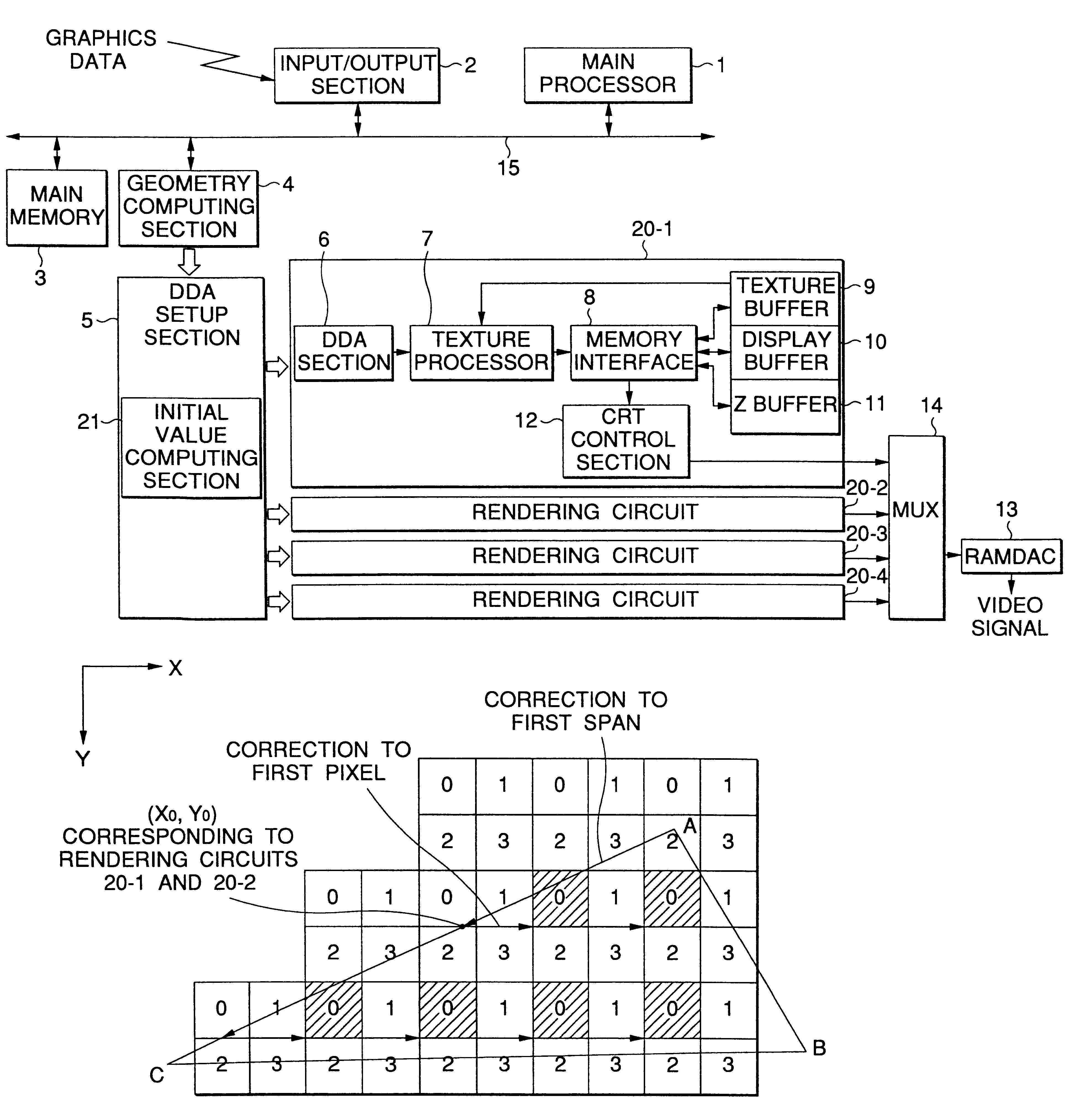
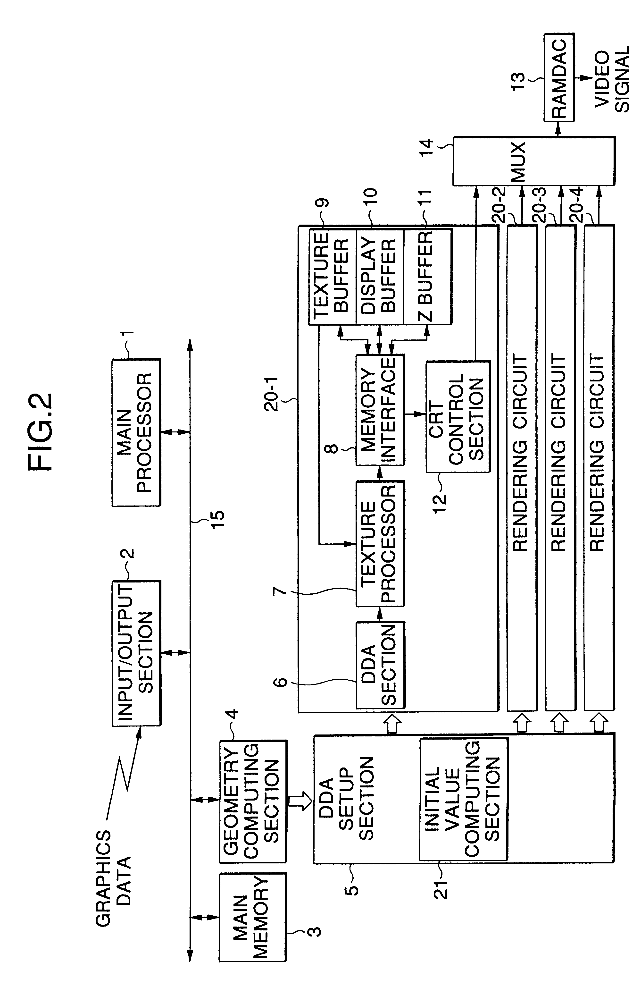
FIG. 2 is a diagram showing a structure of one embodiment of the inventive rendering system. A main processor 1 outputs graphic data supplied via an input / output section 2 or polygon graphic data stored in a main memory 3 to a geometry computing section 4. It is noted that such polygon graphic data is generated in accordance to a predetermined application program.

The geometry computing section 4 implements such processes as coordinate transformation, clipping, writing and the like to the graphic data supplied from the main processor 1 and outputs, as graphics data (polygon rendering data) after the processing, coordinates X, Y and Z corresponding to each apex of a triangular polygon, values of brightness R, G and B corresponding to red, green and blue, respectively, a coefficient of blend a representing a ratio in which a value of brightness of a pixel to be drawing and a value of brightness of a pixel stored in a display buffer 10, texture coordinates S, T and Q, and a coefficient ...


PUM

PropertyMeasurementUnit
areasaaaaaaaaaa
processabilityaaaaaaaaaa
shapeaaaaaaaaaa

Abstract

There is provided a rendering system for processing pixels corresponding to a predetermined graphic in parallel by dividing a two-dimensional image coordinate system into areas each composed of a plurality of pixels of N pixels in a first direction and M pixels in a second direction perpendicular to the first direction, i.e. NxM pixels in total, and by allocating NxM computing sections respectively to the NxM pixels contained in that area. Specifically, the rendering system comprises a calculating section for calculating variations of the rendering data with respect to the first and second directions necessary for interpolating values of the rendering data in each pixel within a predetermined graphic from predetermined apex data of the predetermined graphic and an initial value of the rendering data with respect to the coordinate in the first direction which becomes the reference for computing the rendering data with respect to the second direction by means of interpolation by using the value of the predetermined apex data and the variation of the rendering data with respect to the first direction; and NxM computing sections for calculating the rendering data of the pixel in the second direction by means of interpolation by using the above-mentioned initial value and the variation of the rendering data with respect to the second direction. Thereby, the present invention allows the pixels to be rendered in parallel at high speed in the definition of sub-pixel level.

Description

1. Field of the InventionThe present invention relates to a rendering method and a rendering system in general and more particularly to a rendering method and a rendering system for drawing pixels corresponding to a predetermined graphic by dividing a two-dimensional image coordinate system into N pixel areas in a first direction and M pixel areas in a second direction which is perpendicular to the first direction, i.e. N.times.M pixel areas in total, and by allocating N.times.M computing sections respectively to the N.times.M pixels in each of the divided areas.2. Description of the Related ArtWith the progress of the resent semiconductor technology, the processability of an image processing system is also increasing.In so-called computer graphics, there is a case when a plurality of two-dimensional graphics (polygons) having a predetermined fundamental shape (e.g. triangle) is used in displaying a three-dimensional object on a display screen.A rendering process is then implemented...

Claims


Application Information

Patent Timeline
Patent Type & Authority Patents(United States)
IPC IPC(8): G06T15/00G09G5/20G06T11/20G06T11/40G09G5/36G11B5/012G11B5/55G11B5/596G11B20/12G11B21/08
CPCG06T11/40G06T15/005G11B5/5526G11B5/59655G11B21/083G11B5/012
Inventor OMORI, MUTSUHIRO
Owner SONY CORP
Why Eureka
Try Eureka